Installation instructions, Sensor harness wiring, Gear selection (important) – Novak Velociti/SS Pro Motor (55-3400-1 Rev.8) User Manual
Page 2: Gearing starting points for 6-cell (2s lipo) use
motor
phase
wire
tab I.D.
text
motor
phase
wire
tab I.D.
text
A
A
B
B
C
C
1. NO MOTOR CAPACITORS & SCHOTTKY NEEDED
Novak brushless motors do not need motor capacitors or external
Schottky diodes--Schottky diode usage will damage ESC.
2. CHECK MOTOR SCREW LENGTH & INSTALL MOTOR
• Insert the motor mounting screws that came with your vehicle
through the motor mounting plate.
540 & 550-size motors need
no more than 1/8” of screw extending past the vehicle’s mounting
plate (2-4mm)--Too little can strip the motor’s threads, too much
will cause internal motor damage & will void warranty.
• Attach motor to vehicle’s motor mount using one of the sets of
threaded mounting holes--
select a mounting position that keeps the
solder tabs clear of conductive surfaces like aluminum or graphite.
3. INSTALL PINION GEAR (see GEAR SELECTION on back)
Install pinion on motor and test fit in vehicle to align pinion and
spur gears. Tighten pinion’s set screw on the flat of motor shaft.
4. ADJUST MOTOR FOR PROPER GEAR MESH
• Adjust the motor position for proper amount of free play. You
NEED to have a small amount of play between the pinion gear
and the spur gear (about the thickness of piece of paper)--check
the free play at several positions around the spur gear to
ensure a proper mesh
(just in case the gears are out of round).
MAKE SURE THE PINION/SPUR GEAR MESH IS NOT TOO TIGHT!
If gear mesh is too tight, motor shaft breakage can occur.
• Tighten motor mounting screws--Avoid using excessive force,
as the threaded holes in motor could become stripped.
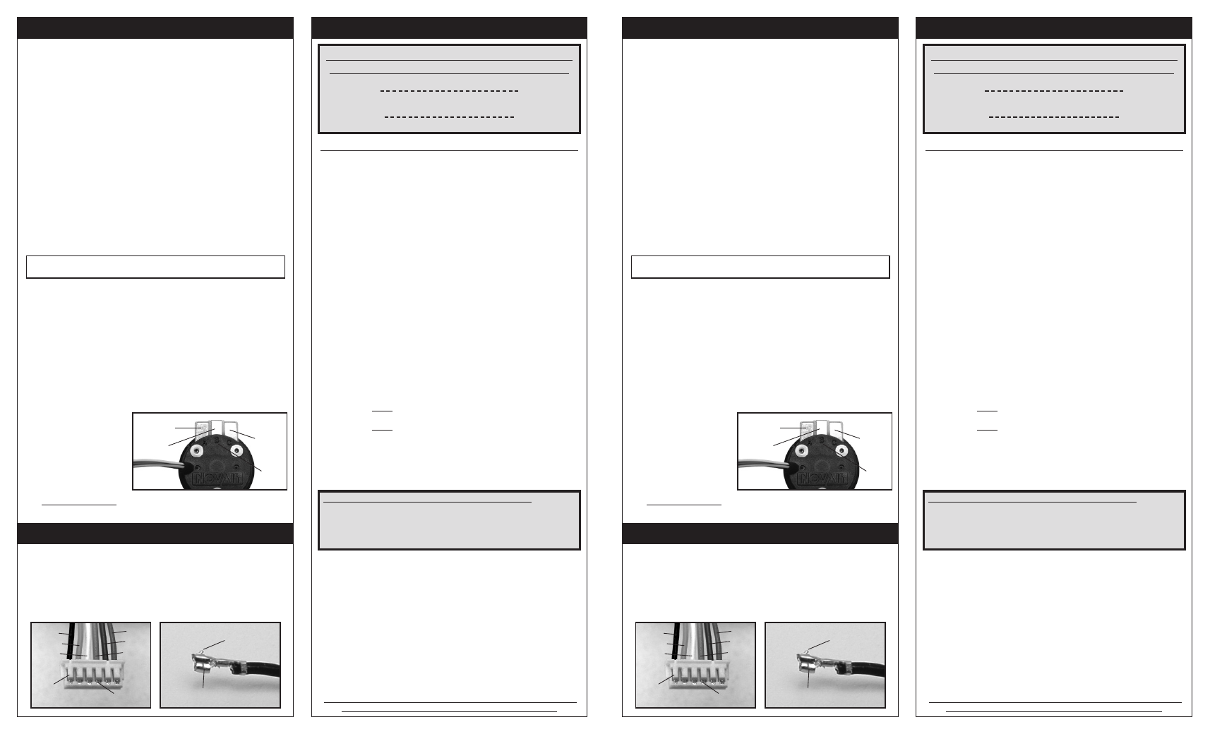
5. SOLDER 540/550 MOTOR WIRES & CONNECT SENSOR HARNESS
• Determine the best routing in vehicle for sensor harness & power
wires. Prepare ends of motor power wires by stripping 1/8-
1/4” of insulation from end of wire. Tin wire ends with solder.
•
Lay tinned end of the wire flat on the solder tab and solder wires
to proper tabs of the motor (see photo below). Apply heat with
soldering iron to the power wire and solder tab--begin adding
solder to tip of iron and to wire--
Add just enough solder to form a
clean & continuous joint from the solder tab up onto the wire.
WARNING: Be sure no wire strands have strayed to an adjacent solder tab--this
will cause short-circuiting, damage electronics, & void product’s warranty.
Be sure to solder wires
to matching tabs at
ESC & Motor
(A/B/C)
IMPORTANT NOTE: DO NOT OVERHEAT SOLDER TABS
Prolonged/excessive heating of solder tabs will damage PCB & void warranty.
1. NO MOTOR CAPACITORS & SCHOTTKY NEEDED
Novak brushless motors do not need motor capacitors or external
Schottky diodes--Schottky diode usage will damage ESC.
2. CHECK MOTOR SCREW LENGTH & INSTALL MOTOR
• Insert the motor mounting screws that came with your vehicle
through the motor mounting plate.
540 & 550-size motors need
no more than 1/8” of screw extending past the vehicle’s mounting
plate (2-4mm)--Too little can strip the motor’s threads, too much
will cause internal motor damage & will void warranty.
• Attach motor to vehicle’s motor mount using one of the sets of
threaded mounting holes--
select a mounting position that keeps the
solder tabs clear of conductive surfaces like aluminum or graphite.
3. INSTALL PINION GEAR (see GEAR SELECTION on back)
Install pinion on motor and test fit in vehicle to align pinion and
spur gears. Tighten pinion’s set screw on the flat of motor shaft.
4. ADJUST MOTOR FOR PROPER GEAR MESH
• Adjust the motor position for proper amount of free play. You
NEED to have a small amount of play between the pinion gear
and the spur gear (about the thickness of piece of paper)--check
the free play at several positions around the spur gear to
ensure a proper mesh
(just in case the gears are out of round).
MAKE SURE THE PINION/SPUR GEAR MESH IS NOT TOO TIGHT!
If gear mesh is too tight, motor shaft breakage can occur.
• Tighten motor mounting screws--Avoid using excessive force,
as the threaded holes in motor could become stripped.
5. SOLDER 540/550 MOTOR WIRES & CONNECT SENSOR HARNESS
• Determine the best routing in vehicle for sensor harness & power
wires. Prepare ends of motor power wires by stripping 1/8-
1/4” of insulation from end of wire. Tin wire ends with solder.
•
Lay tinned end of the wire flat on the solder tab and solder wires
to proper tabs of the motor (see photo below). Apply heat with
soldering iron to the power wire and solder tab--begin adding
solder to tip of iron and to wire--
Add just enough solder to form a
clean & continuous joint from the solder tab up onto the wire.
WARNING: Be sure no wire strands have strayed to an adjacent solder tab--this
will cause short-circuiting, damage electronics, & void product’s warranty.
Be sure to solder wires
to matching tabs at
ESC & Motor
(A/B/C)
IMPORTANT NOTE: DO NOT OVERHEAT SOLDER TABS
Prolonged/excessive heating of solder tabs will damage PCB & void warranty.
INSTALLATION INSTRUCTIONS
INSTALLATION INSTRUCTIONS
black
orange
white
black
orange
white
plastic
tabs
plastic
tabs
red
blue
green
red
blue
green
metal
barbs
metal
barbs
raised
metal
barb
raised
metal
barb
metal socket on end of
Teflon sensor harness wires
metal socket on end of
Teflon sensor harness wires
Should any of the 26G Teflon wires pull out of the motor’s sensor
harness connector, re-insert them in the connector’s appropriate
slot as shown below. There is a small plastic tab that grabs a small
raised barb on the back of the metal socket crimped onto the Teflon
wire’s end. Check the plastic tab to make sure it has not deformed
excessively before inserting the socket into the plastic connector
housing with the barb toward the plastic tabs.
SENSOR HARNESS WIRING
SENSOR HARNESS WIRING
Motor operating temperature is the ONLY
way to properly set the vehicle gearing
The motor should be 160-175°F MAX at end of run!
Temperatures above 175°F will weaken the magnet & may
melt the coils! This voids warranty & can damage ESC!
Change the gearing to avoid overheating.
Gearing Starting Points for 6-Cell (2S LiPo) Use:
Velociti 3.5R motor
4 teeth lower pinion than normally used on 7-turn brush motor.
Velociti 3.5L (Light) motor
5 teeth lower pinion than normally used on 7-turn brush motor.
Velociti 4.5R motor
4 teeth lower pinion than normally used on 8-turn brush motor.
Velociti 4.5L (Light) motor
5 teeth lower pinion than normally used on 8-turn brush motor.
Velociti 5.5R motor
3 teeth lower pinion than normally used on 9 or 10-turn brush motor.
Velociti 5.5L (Light) motor
4 teeth lower pinion than normally used on 9 or 10-turn brush motor.
Velociti 6.5R motor
2 teeth lower pinion than normally used on 10 or 11-turn brush motor.
Velociti 6.5L (Light) motor
3 teeth lower pinion than normally used on 10 or 11-turn brush motor.
Velociti 7.5R motor
1 tooth lower pinion than normally used on 12 or 13-turn brush motor.
Velociti 7.5L (Light) motor
2 teeth lower pinion than normally used on 12 or 13-turn brush motor.
SS-Pro 8.5 motor
1-2 teeth lower pinion than normally used on 15-turn brush motor.
SS-Pro 10.5 motor
1-2 teeth lower pinion than normally used on 19-turn brush motor.
SS-Pro 13.5 motor
1-2 teeth lower pinion than normally used on 27-turn brush motor.
SS-Pro 17.5 motor
1-2 teeth bigger pinion than normally used on 27-turn brush motor.
SS-Pro 21.5 motor
2-3 teeth bigger pinion than normally used on 27-turn brush motor.
Havoc 8.5, EX 8.5, or SS 5800 motor
3-4 teeth lower pinion than normally used on 15-turn brush motor.
EX 10.5 or SS 4300 motor
3-4 teeth lower pinion than normally used on 19-turn brush motor.
EX 13.5 motor
3-4 teeth lower pinion than normally used on 27-turn brush motor.
If you do not change gearing after switching to brushless, you will be
over-geared and will have slow acceleration & excessive temperatures!
Because of the broad power band of brushless, you can go 1-2 teeth higher pinion
than the above recommendations for more top speed, but remember any higher will
produce excessive ESC & motor heating. Check motor’s operating temperature after
making gearing adjustments--motors are designed to operate from 160ºF-175ºF.
Crawler Brushless Motors
When properly geared for use with gear reduction transmissions found in rock
crawling vehicles, your brushless crawler motor and ESC should not get very
hot--if you notice excessive temperatures, check motor & drive train for free
operation or adjust gearing to lower temperature.
Three-80 Micro Pro Brushless Motors
A safe starting point for gearing is 3-5 teeth smaller than the stock pinion gear
that came with your micro vehicle. When properly geared, your Three-80 system
should not get excessively hot--if you notice high temperatures, check motor &
drive train for free operation or adjust gearing to lower temperature.
HV (550-size high-voltage) Brushless Motors
Novak HV motors should be geared based on the end-of-run motor & ESC
temperatures--adjust gearing so the temperatures do not exceed 160-170°F.
If installing in the Traxxas
®
E-Maxx
TM
, start with the following:
Original E-Maxx
TM
:
72 spur gear
12T pinion
New version E-Maxx
TM
:
68 spur gear (stock) 12T pinion
See our website for updated gearing recommendations, final
drive ratios, or if your motor does not appear above.
GEAR SELECTION (Important)
GEAR SELECTION (Important)