Basic set-up photo, Max timing advance, Timing start rpm – Novak Oval Spec 1S Set-Up (55-1743-1.2) User Manual
Page 2: Timing end rpm, Timing range, Drive frequency, Minimum drive, Dead band, Hall sensor test, Esc programming
Receiver
harness
ON/OFF
switch
black
wire
(negative)
red wire
(positive)
white wire
(signal)
Fan power
output pins
black wire
(negative)
ADJUSTABLE pARAMETERS
max timing advance
#1 MAXIMUM TIMING ADVANCE
(1 of 11 in 3 RPM Ranges)
BLUE LED
The maximum degrees of Dynamic Timing Advance applied to the motor.
>> Increasing this setting increases the maximum amount of electronic motor
timing applied to the motor. Select 1 of the 3 Timing Ranges in Parameter #4.
Setting
(# of flashes)
1
2
3
4
5
6
7
8
9 10 11
Low Range
(degrees)
: Off 26 27 28 29 30 31 32 33 34 35
Mid Range
(degrees)
: Off 36 37 38 39 40 41 42 43 44 45
High Range
(degrees)
: Off 46 47 48 49 50 51 52 53 54 55
TIMING START RPM
#2 START RPM SELECTION
(1 of 10)
YELLOW LED
The RPM point at which Dynamic Timing Advance starts to be applied.
>> Increasing this setting raises the RPM when electronic timing comes ON.
Setting
(# of flashes)
1
2
3
4
5
6
7
8
9
10
Start RPM:
Low
--
--
-->
--
--
-->
--
--
High
TIMING END RPM
#3 END/FINAL RPM SELECTION
(1 of 10)
GREEN LED
The RPM point at which Dynamic Timing Advance reaches the maximum timing.
>> Increasing this setting raises the RPM set point at which the electronic
motor timing reaches the maximum advancement
(setting #1 above).
Setting
(# of flashes)
1
2
3
4
5
6
7
8
9
10
End/Final RPM:
Low
--
--
-->
--
--
-->
--
--
High
timing range
#4 TIMING RANGE SELECTION
(1 of 3)
WHITE LED
The range of selectable degrees of Dynamic Timing Advance for Parameter #1.
Setting
(# of flashes)
1
2
3
RPM Range:
Low
Mid
High
DRIVE FREQUENCY
#5 DRIVE FREQ. SELECTION
(1 of 10)
BLUE/YELLOW/GREEN LEDs
How the ESC’s throttle response feels with respect to the transmitter’s trigger input.
>> Increasing this setting makes the throttle response feel more aggressive.
Setting
(# of flashes)
1
2
3
4
5
6
7
8
9 10
Drive Freq. (kHz):
32 31 30 29 28 27 26 25 24 23
MINIMUM DRIVE
#6 MIN. DRIVE SELECTION
(1 of 10)
BLUE/YELLOW/RED LEDs
Amount of forward drive applied with the first pulse of transmitter information sent.
>> Increasing this setting starts the forward drive at a higher level.
Setting
(# of flashes)
1
2
3
4
5
6
7
8
9 10
Minimum Drive (%):
1
4
6
8
10 12 16 18 20 22
DEAD BAND
#7 DEAD BAND SELECTION
(1 of 5)
BLUE/YELLOW/WHITE LEDs
The space between Minimum Brake and Minimum Drive, with Neutral in the middle.
>> Increasing this setting increases the amount of ‘free play’, or distance your
transmitter’s trigger must move before forward drive or braking begins.
Setting
(# of flashes)
1
2
3
4
5
Dead Band (%):
2
3
4
5
8
hall sensor test
MOTOR SENSOR TEST
BLUE LED FLASHING
>> Diagnostic feature to check functionality of brushless motor’s hall effect
sensors & harness/connections at ESC & motor. Once activated, slowly rotate the
motor’s output shaft--Appropriate LED will light up if sensor signal is received.
Sensor
(color flashing)
A
B
C
LED Color:
BLUE
YELLOW
RED
Note: ESC Parameter values are subject to change due to ongoing development. Refer to our web site for updated values and more information on ESC parameters.
basic set-up photo
w
w
w
.t
ea
m
n
ov
a
k
.c
om
step 2–connect motor
step 1–mount esc
Mount the speed control so that the power wires will not interfere with the
vehicle’s moving parts. Select an installation location that has good airflow
for cooling the ESC as this will result in more efficient operation.
1. MOUNT SPEED CONTROL IN VEHICLE
Mount the ESC to the vehicle’s chassis using the included double-sided
tape (do NOT use glue). Avoid contact with the chassis side walls or other
vehicle components to avoid vibration damage.
Keep receiver and antenna as far from ESC, power wires, battery, & servo
as possible--These components all emit RF noise.
Note: Mount antenna as close to receiver as possible--trail excess wire off top of
antenna mast (cutting/coiling excess wire reduces radio range--2.4GHz too).
2. INSTALL ON/OFF SWITCH/PROGRAMMING BUTTON
Mount the ESC’s ON/OFF switch/button with the included double-sided
tape to where it will be easy to access--select a place where it will not get
damaged/switched OFF in a crash.
If using an External Receiver Pack: The programming button/switch
harness can be removed from the ESC during operation--You must use an
input signal harness with a RED wire in it to supply power to the ESC.
3. SECURE POWER WIRES TO AVOID VIBRATION DAMAGE
To prevent vibration damage, use the included tie-wraps to secure the
speed control’s PowerCap module and battery & motor power wires
together and/or to a point on the vehicle to help prevent vibration and
stress on the ESC’s solder joints and the solder tabs.
1. INSTALL PINION GEAR
Tighten the pinion gear’s set screw onto the flat of the motor shaft. Align
the pinion and the spur gears.
2. ADJUST MOTOR FOR PROPER GEAR MESH
A. You NEED a small amount of free play between the pinion and spur
gear (about the thickness of a piece of paper)--check for free play at
several points around spur gear to ensure a proper mesh
(Make sure
the gear mesh is NOT TOO TIGHT).
B. Tighten the motor mounting screws--Avoid using excessive force that
could break the screws or strip the threaded holes in motor.
3. CONNECT MOTOR POWER WIRES TO MOTOR
The motor power wires are all the same color, therefore refer to the Phase
markings that are stamped on the ESC’s case under the solder tabs.
A.
Connect the ESC’s
Phase ‘A’ silicone motor power wire to the motor’s
Phase A solder tab.
B.
Connect the
Phase ‘B’ power wire to motor’s Phase B solder tab.
C.
Connect the
Phase ‘C’ power wire to motor’s Phase C solder tab.
4. CONNECT MOTOR SENSOR HARNESS TO ESC
Insert the 6-pin connector of the motor’s sensor harness into ESC’s sensor
harness socket—connector is keyed and only inserts in one direction.
5. CHECK FOR PROPER GEARING DURING INITIAL RUNS
ESC/Motor should never exceed 160°F--Lower gearing or check vehicle’s drive
train for binding or other problems if you experience high temperatures.
With ESC connected to a charged battery, receiver, & motor’s sensor harness:
1. TURN ON THE TRANSMITTER’S POWER
2. PRESS & HOLD ESC’S ONE-TOUCH/SET BUTTON
(Re-install ON/OFF switch/programming harness if it was removed for operation)
3. TURN ON THE SPEED CONTROL’S POWER
With transmitter trigger at neutral (and still pressing the SET button), slide
the ESC’s switch
to the ON position.
4. CONTINUE HOLDING SET BUTTON UNTIL RED LED COMES ON
5. RELEASE SET BUTTON AS SOON AS RED LED TURNS ON
6. PULL TRANSMITTER THROTTLE TO FULL-ON POSITION
Hold it there until the green status LED
turns solid green
(motor will not run).
7. PUSH TRANSMITTER THROTTLE TO FULL-BRAKE/REVERSE
Hold it there until the green status LED
blinks green.
8. RETURN TRANSMITTER THROTTLE TO NEUTRAL
The red status LED will
turn solid red, indicating that speed control is at
neutral and that proper programming has been completed.
If transmitter settings are changed, the One-Touch Programming must be repeated.
If you experience any problems, turn off ESC and repeat One-Touch.
NOTE: One-Touch Programming reverts ESC back to factory-default settings.
STEP 5-one-touch programming
transmitter adjustments
ESC programming -->
Transmitter adjustments may not be needed to properly complete the ESCs
One-Touch programming--if you have any problems with the programming,
adjust transmitter as listed below and repeat
ONE-TOUCH PROGRAMMING.
THROTTLE CHANNEL ADJUSTMENTS
A. Set HIGH ATV
or
EPA
to 100%. [amount of throw at full throttle]
B. Set LOW ATV, EPA, or ATL
to 100%. [amount of throw at full brakes]
C. Set EXPONENTIAL
to
zero setting.
[throttle channel linearity]
D. Set THROTTLE CHANNEL REVERSING SWITCH
to either position.
E. Set THROTTLE CHANNEL TRIM
to
middle
.
[adjusts neutral position]
F. Set ELECTRONIC TRIGGER THROW
to 70% throttle/30% brake (or 7:3)--best
for racing. Set to 50%/50% for full time use with reverse for best performance.
G. Set MECHANICAL TRIGGER THROW
to 2/3 throttle and 1/3 brake throw position.
•NOT ALL TRANSMITTERS HAVE ALL OF THESE ADJUSTMENTS•
step 3–connect receiver
The ESC has a user-replaceable input harness
with a 2mm mini plug on ESC end of it and the
industry-standard connector on receiver end.
The ESC works with all major radio brand’s
new receivers. Some very old receivers need
the wiring sequence changed in the plastic
3-pin connector on the receiver end--
Receiver/
servo may be damaged if sequence is incorrect.
For instructions on changing the wiring
sequences on older receivers, visit our web site.
1. CONNECT 2mm MINI PLUG TO RECEIVER HARNESS PINS ON ESC
Insert 2mm mini plug of receiver input harness onto ESC’s 3-pin Rx header.
•If using receiver pack/booster with ESC’s switch/button harness INSTALLED:
Remove RED wire from receiver input signal harness and leave ESC’s switch ON.
•If using external receiver battery with ESC’s switch/button harness REMOVED:
Use receiver input signal harness wire RED wire intact to power ESC’.
2. CONNECT RECEIVER HARNESS TO RECEIVER
Insert 3-pin connector of receiver harness into Ch.2 (throttle) slot of receiver.
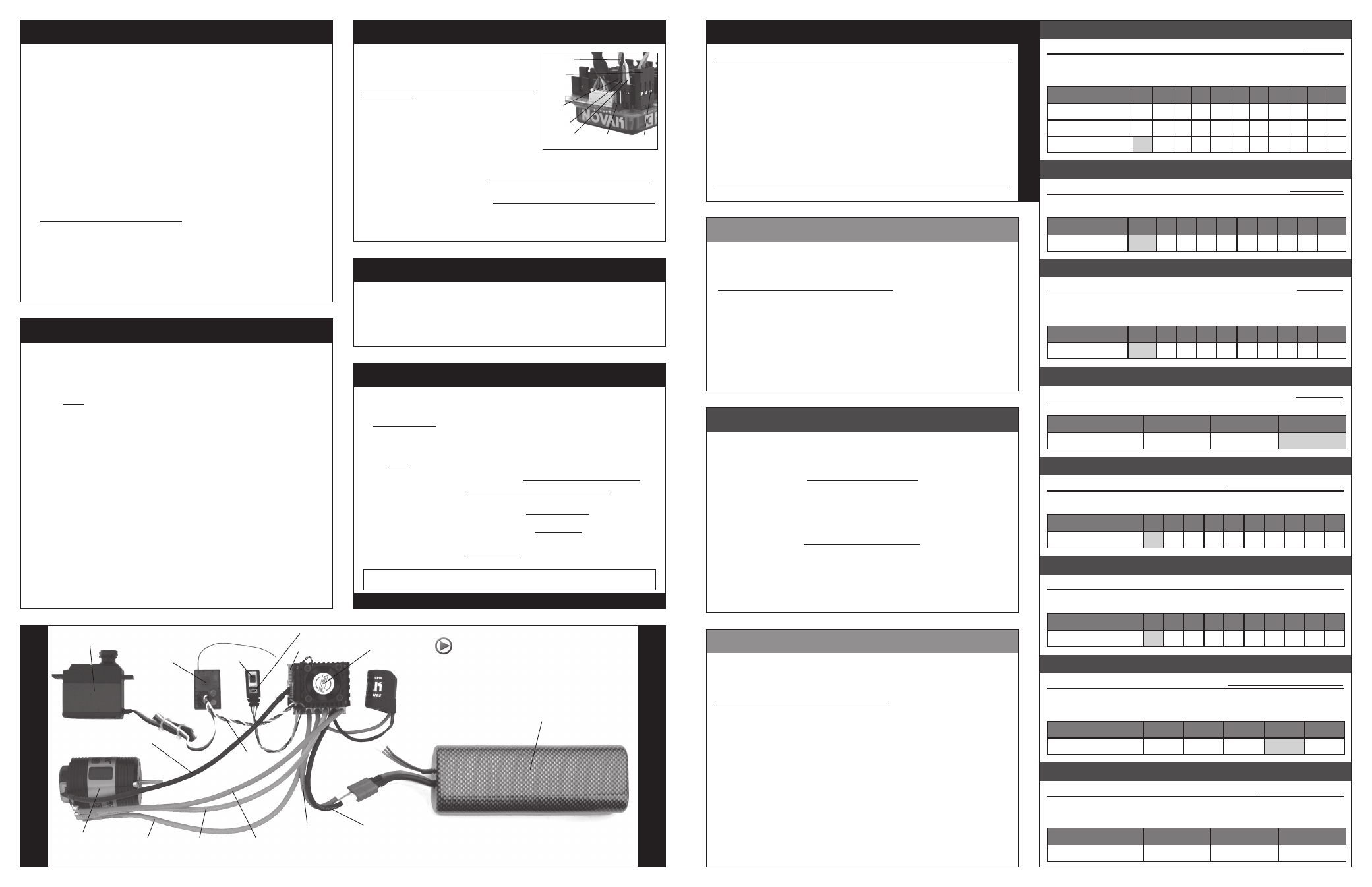
ON/OFF Switch
input signal
harness
(Ch.2)
Servo plugged into
steering channel
(Ch.1)
Set button
Status LEDs
*Cooling fan
not included
Receiver
Sensor-based
brushless motor
Phase A
motor wire
Phase B
motor wire
Red battery wire
(positive)
Black
battery wire
(negative)
1S LiPo Battery pack
For informative installation and how-to videos,
visit the Team Novak Channel on YouTube®.
*Note: Battery pack, servo, and receiver are not included.
motor hall sensor test
step 4–connect battery
1. CONNECT BATTERY POWER WIRES TO BATTERY PACK
Connect a fully charged, high-quality 1S LiPo battery pack to the speed
control’s
BLACK (positive) and RED (negative) battery power wires.
To use a battery connector on ESC, we suggest using polarized, low-loss, high
power connectors like Dean’s Ultra Plug. Use a female connector on battery.
Phase C
motor wire
Brushless motor
sensor harness
The Hall Sensor Test diagnostic feature allows you to easily check the sensors in the
brushless motor connected to the ESC to determine if they are operating normally.
This helps you pinpoint the cause of system problems, and reduce down time and
customer service expenses when you can resolve the issue yourself.
To access this feature, simply follow these steps:
1. Follow the steps in the ‘ESC PROGRAMMING’ section to access the Hall
Sensor Test option via the ESC’s SET button.
2. Slowly rotate the motor’s output/pinion shaft. If motor is installed in a
vehicle, slowly rotate the drive train so that the motor also rotates.
3. As the motor is rotated, the BLUE, YELLOW, and RED status LEDs on the
speed control should cycle through illuminating and going off.
If the BLUE, YELLOW, and RED LEDs light up & go off, one after another as the
motor’s shaft is rotated, the Hall Sensors in the motor are operating normally.
If any one of the BLUE, YELLOW, or RED status LEDs do not light, or remain on as the
shaft is rotated, there is a either a problem with the Sensor Harness (or its motor or
ESC end connections) or with the Hall Effect Sensors in the motor’s timing section.
If your motor has a user-replaceable double-ended sensor harness, replace it with
another one to determine if this is the problem. If, after replacing the harness, all
3 of the LEDs still do not light up, it would appear that one of the motor’s sensors
has been damaged--replace the timing section of your motor, or if your motor
is not user-rebuildable, send it in the manufacturer for the appropriate service.
TO CHANGE THE SETTINGS OF THE ‘ADJUSTABLE PARAMETERS’:
1. CONNECT THE ESC TO A CHARGED BATTERY PACK & RECEIVER.
2. TURN ON TRANSMITTER & SLIDE ESC’s POWER SWITCH TO ‘ON’ POSITION
3. WITH ESC AT NEUTRAL, PRESS & HOLD ESC’s SET BUTTON
Release ESC’s SET button once the LED is lit for the setting you wish to change.
To skip, continue to press & hold SET button until desired parameter is reached.
4. SELECT PARAMETER VALUE
(refer to tables in ‘Adjustable Parameters’ to the right)
LED flashes to indicate active setting. Quick press & release button to change.
5. PRESS & HOLD SET BUTTON TO STORE NEW SELECTION
When button is pressed & held for 1 second,
new selection is stored in ESC’s
memory. Status LEDs will scroll across to confirm ESC programming & ESC returns to neutral.
DEFAULT PARAMETER SETTINGS ARE LISTED IN BOLD IN THE TABLES TO THE RIGHT
There is no time constraint during selection of custom parameters.
Use of an external receiver pack or booster circuit is recommended for the
best performance with this speed control, as the receiver & servo require
more voltage than a 1S LiPo battery can supply.
External Receiver Pack:
Plug receiver battery pack into an open/unused slot of your receiver.
Remove the RED wire from the plug plastic on the ESC’s receiver input signal
harness, and leave the ESC’s ON/OFF switch in the ‘ON’ position at all times.
--or--
Remove the ON/OFF switch/programming button harness from speed control
completely (re-install the harness for ESC programming).
External Booster Circuit:
Plug booster circuit’s receiver output lead into an open/unused slot of receiver.
Remove the RED wire from the plug plastic on the ESC’s receiver input signal
harness. Use the booster’s ON/OFF switch to turn the system’s power ON & OFF,
and leave the ESC’s ON/OFF switch in the ‘ON’ position at all times
--or--
Remove the ON/OFF switch/programming button harness from speed control
completely (re-install the harness for ESC programming).
receiver pack /booster
•ESC has 3 Blue motor phase wires--See case markings for Phase•