Step, Transmitter adjustments, Connect input harness – Novak Mongoose Basic Set-Up (55-3050-1) User Manual
Page 2: Do not use schottky diodes, Brushless-mode set -up photo, Esc mounting, Wiring speed control, motor, & battery, One-touch programming, Brush-mode set -up photo, Sensor harness wiring
*If motor has no ground tab
(as shown here), solder the
capacitors to motor can.
•NOT ALL TRANSMITTERS HA
VE THESE ADJUSTMENTS
•
The Mongoose has a user-replaceable input harness with the industry-standard
receiver connector on it &
works with all major radio brand’s new receivers.
However, some very old receivers must have the wiring sequence in the plastic
3-pin JST connector housing changed on the receiver end.
This is important, as
the receiver & servo electronics may be damaged if the sequence is incorrect.
JR • Hitec • Futaba • New KO • Airtronics Z
JR, Hitec, Futaba, new KO, & Airtronics Z receivers do not need input
harness re-wiring. Airtronics Z receivers have blue plastic cases & new KO
cases have tabs on the input harness openings as in
Figure 1.
• Plug the larger JST end of the input signal harness into the THROTTLE CHANNEL
(#2) of receiver with the
BLACK wire toward the outside edge of receiver case.
• Plug the end of the input harness with the smaller 2mm connector into 3-pin
header on the speed control’s PC board with the
WHITE wire toward the left
edge of the ESC’s case.
Old-style KO • Old-style Sanwa/Airtronics
If you have an older KO or Sanwa/Airtronics, you must change the sequence
of the ESC’s input harness wires on the receiver end--Old Sanwa/Airtronics cases
are black color & Old KO cases do not have tab openings, as in
Figure 2 above.
• Using a small flat blade screwdriver,
remove the red & black wires from the plastic
JST connector at the receiver end of the input harness as in
Figure 3 below.
•
Interchange the red and black wires in the plastic 3-pin connector housing at
the receiver end of the input harness.
• Insert modified end of the harness into the THROTTLE CHANNEL (#2) of receiver
with the
RED wire toward the outside edge of receiver case.
• Plug the other end of the input harness into the ESC with the
WHITE wire toward
the left edge of the ESC’s case.
FIGURE 3
With a small standard screwdriver, gently lift plastic prong
until wire and metal socket easily slide out of plastic housing.
changing wiring sequence
@
receiver end
FIGURE
1
FIGURE
2
New KO (with tabs)
Old KO (no tabs)
tabs
no tabs
black
red
red
white
black
white
P3
step
1
–
connect input harness
1. MOTOR CAPACITORS NOT NEEDED
Novak brushless motors do not require external motor capacitors.
2. DO NOT USE SCHOTTKY DIODES
Schottky diodes must NOT be used with reversible ESCs (including brushless).
Schottky diode usage will damage the ESC & void warranty.
3. FACTORY-INSTALLED POWER CAPACITOR REQUIRED
The factory-installed Power Capacitor MUST be used with brushless &
brush-type motors.
If Power Capacitor becomes dented or damaged, ESC failure can
occur--replace immediately. Longer Power Capacitor wires will decrease performance.
4. CONNECT ESC’S MOTOR PHASE WIRES TO MOTOR
The Mongoose comes with high quality 2mm low-loss power connectors
on the motor wires. Connect the ESC’s power phase wires to the matching
color motor power wires.
a. Connect the BLUE ESC power wire to the BLUE motor wire.
b. Connect the YELLOW ESC power wire to the YELLOW motor wire.
c. Connect the ORANGE ESC power wire to the ORANGE motor wire.
Additional 2mm power connectors available in Novak accessory kits.
5. CONNECT MOTOR’S SENSOR HARNESS TO ESC
Insert the 6-pin connector on the end of the motor’s Teflon sensor wires
into ESC’s sensor harness socket--the connector is keyed and will only go
together in one direction.
6. CONNECT SPEED CONTROL TO BATTERY PACK
Connect the speed control’s
BLACK and RED power wires to a charged 4
to 9 cell (1.2VDC/cell) or 2-3 cell LiPo battery pack. Connect the
RED to
battery pack
POSITIVE (+) and the BLACK to battery pack NEGATIVE (-).
CHECK FOR PROPER GEARING
Proper brushless motor gearing is determined by motor & ESC
temperatures during and at the end of the run.
Refer to the ‘PROPER GEAR SELECTION’ portion of the CUSTOM PROGRAMMING
Sheet (Pg.5) to determine proper gearing & avoid overheating.
1. DISCONNECT BRUSHLESS MOTOR SENSOR HARNESS
The Mongoose automatically switches to Brush-Mode when the ESC power
is switched ON and no brushless sensor harness is connected.
2. MOTOR CAPACITORS
Electric brush-type motors generate RF noise that causes interference. Three
0.1µF (50V) non-polarized, ceramic capacitors must be used on all motors
to reduce motor noise & prevent ESC damage (3 included with ESC).
Note: Some motors come with factory-installed capacitors. If your motor only has 2
capacitors, you need to install a capacitor between the positive & negative motor tabs.
Solder 0.1µF (50V) capacitors between:
• POSITIVE (+) & NEGATIVE (–) motor tabs.
• POSITIVE (+) motor tab & GROUND tab*.
• NEGATIVE (–) motor tab & GROUND tab*.
Negative (–) motor tab
0.1µF Capacitors
Positive (+) motor tab
Ground
(motor can)
DO NOT USE SCHOTTKY DIODES
3. CONNECT ESC’S BLUE & YELLOW WIRES TO MOTOR
With brush-type motors, the ESC’s BLUE power wire goes to the NEGATIVE (–)
Motor Tab & the YELLOW power wire goes to the POSITIVE (+) Motor Tab.
a. Connect the BLUE ESC power wire to the NEGATIVE (–) Motor Tab.
b. Connect the YELLOW ESC power wire to the POSITIVE (+) Motor Tab.
Additional Novak 2mm low-loss power connectors available from www.teamnovak.com
4. CONNECT SPEED CONTROL TO BATTERY PACK
Connect the speed control’s
BLACK and RED power wires to a charged 4
to 9 cell (1.2VDC/cell) or 2-3 cell LiPo battery pack. Connect the
RED to
battery pack
POSITIVE (+) and the BLACK to battery pack NEGATIVE (-).
FIGURE
5
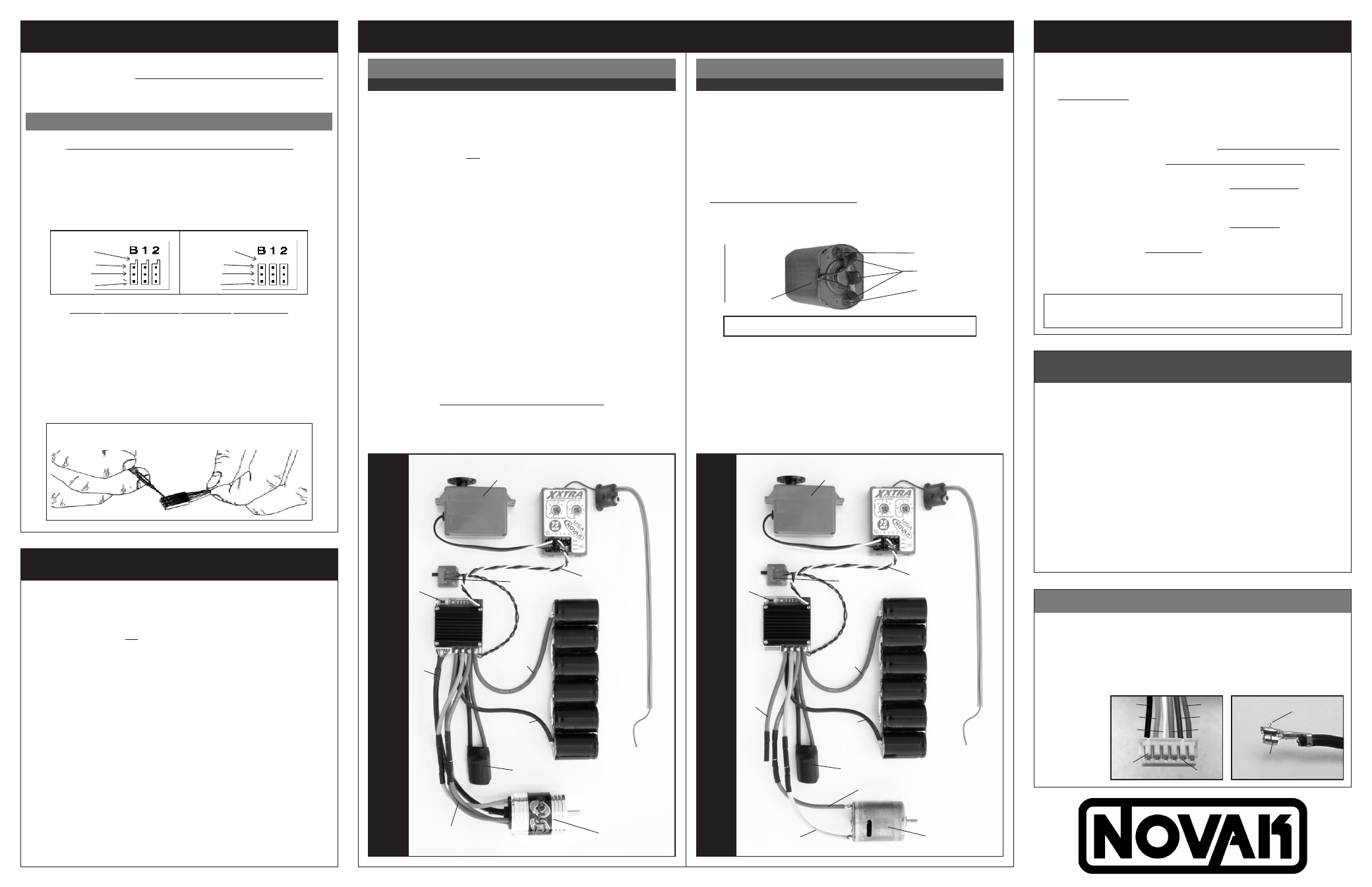
BRUSHLESS-MODE SET
-UP PHOTO
(FIGURE 4)
ON/OFF
Switch
User-replaceable
input signal
harness (Ch.2)
Black
power wire
(bat.negative)
Trail excess wire off top of antenna mast
Red power wire
(batter
y positive)
Blue, Yellow, & Orange
motor phase wires
(–)
(+)
4 to 9 cell batter
y pack or 2-3 cell LiPo
Sensor Harness
Servo plugged into
steering ch. (#1)
Novak Three-80
sensor-based
brushless motor
P2
One-T
ouch
button
Power Cap
module
Blue motor phase wire
to motor negative
(–)
(+)
380-size (or smaller)
brush-type motor
step
2
–
ESC MOUNTiNG
Mount the speed control so that the power wires are as far from other
electronics as possible. Make sure that the speed control or the power
wires will not interfere with any moving parts in the vehicle. Select a
location that has good cooling and allows airflow through heat sinks.
If the ESC gets air flow, it will run cooler; and that means it will be more efficient!
1. MOUNT SPEED CONTROL IN VEHICLE
Use the included double-sided tape to mount the speed control in
vehicle (do not use glue). Avoid contact with side walls or other chassis
components to avoid vibration damage.
Be sure receiver & antenna are mounted as far from ESC, power wires, battery,
& servo as possible--these components all emit RF noise when throttle is
applied. On graphite or aluminum chassis vehicles, it may help to place
receiver on edge with crystal & antenna as far above chassis as possible.
Note: Mount antenna as close to receiver as possible--trail any excess wire off top
of antenna mast (cutting or coiling excess antenna wire will reduce radio range).
2. SECURE POWER CAPACITOR TO CHASSIS
Use included double-sided tape, or a tie-wrap, to mount Power
Capacitor to the vehicle’s chassis or shock tower. Capacitor can also
be tie-wrapped along the power wires--this requires less space on the
chassis and provides good isolation from vibration.
3. INSTALL ON/OFF SWITCH
Use a screw or a piece of the included double-sided tape, and
mount the switch where it will be easy to access--be sure to select
a position where it will not get damaged or get switched OFF in a
crash or during a roll-over.
step
3
–
wirinG speed control, motor, & battEry
NOvak bRuSHlESS mOtOrS
(Fig.4)
Amber LED flashes 4 times at start-up when transmitter signal is present
bRuSH-typE mOtOrS
(Fig.5-6)
Red LED flashes 4x at start-up when ESC is is Brush-Mode (trans.on)
step
4
–
one-touch programming
transmitter adjustments
If you have any problems with Step 4, adjust transmitter as follows
and then repeat the One-Touch programming in Step 4:
A. Set HIGH ATV or EPA to maximum setting.
[amount of throw at full throttle]
B. Set LOW ATV, EPA, or ATL to maximum setting.
[amount of throw at full brakes]
C. Set EXPONENTIAL to zero setting.
[throttle channel linearity]
D. Set THROTTLE CHANNEL REV. SWITCH to either position.
E. Set THROTTLE CHANNEL TRIM to middle setting.
[adjusts neutral position/increases or decreases coast brakes]
F. Set ELECTRONIC TRIGGER THROW ADJUSTMENT to 50%
throttle and 50% brake throw--best for reversible ESCs.
[adjusts trigger throw electronic/digital pistol-grip transmitters]
G. Set MECHANICAL TRIGGER THROW ADJUSTMENT to position
with 1/2 throttle and 1/2 brake throw.
With ESC connected to
(at least)
a receiver & a charged battery pack:
1. TURN ON THE TRANSMITTER’S POWER
2. PRESS & HOLD ESC’S ONE-TOUCH/SET BUTTON
3. TURN ON THE SPEED CONTROL’S POWER
With transmitter throttle at neutral, and still pressing the SET button,
slide the ESC’s ON/OFF switch
to ON position.
4. CONTINUE HOLDING SET BUTTON UNTIL RED LED COMES ON
5. RELEASE SET BUTTON AS SOON AS LED TURNS RED
6. PULL TRANSMITTER THROTTLE TO FULL-ON POSITION
Hold it there until the green status LED
turns solid green.
Note: Motor will not run during programming even if connected.
7. PUSH TRANSMITTER THROTTLE TO FULL-BRAKE/REVERSE
Hold it there until the green status LED
blinks green.
8. RETURN TRANSMITTER THROTTLE TO NEUTRAL
Red status LED will
turn solid red, indicating that speed control is
at neutral and that proper programming has been completed.
NOTE: If transmitter settings are changed, One-Touch Programming must be
repeated. If you experience any problems, turn off ESC & repeat One-Touch.
REMEMBER: Whenever the One-Touch set-up is performed, the speed
control will automatically revert back to the factory default settings & the
Throttle Profile will revert to #1 when in Brushless-Mode.
sensor harness wiring
Should any of the 26G Teflon wires pull out of the connector on the
end of the motor’s sensor harness, re-insert them in the appropriate
slot in the connector as shown below. There is a small plastic tab that
grabs a small raised barb on the back of the metal socket crimped onto
the Teflon wire’s end. The plastic tab should be checked to make sure it
has not deformed excessively before inserting the metal socket into the
plastic connector housing with the barb toward to plastic tabs.
If the motor’s
sensor harness
gets damaged,
please contact
our Customer
Service Dept.
black
orange
white
plastic
tabs
red
blue
green
metal
barbs
raised
metal
barb
metal socket
on end of Teflon
sensor harness wires
BRUSH-MODE SET
-UP PHOTO
(FIGURE 6)
Yellow motor phase wire
to motor positive
ON/OFF
Switch
User-replaceable
input signal
harness (Ch.2)
Black
power wire
(bat.negative)
Trail excess wire off top of antenna mast
Red power wire
(batter
y positive)
(–)
(+)
4 to 9 cell batter
y pack or 2-3 cell LiPo
Servo plugged into
steering ch. (#1)
One-T
ouch
button
Power Cap module
Orange motor phase wire not used in Brush-Mode