Step 4–wire esc to motor, Step 2–mount esc, Step 5–wire esc to battery – Novak Kinetic Basic Set-Up (55-1740-1 Rev.2) User Manual
Page 2: Kinetic 1s set -up photo, Kinetic 2s set -up photo, Step 1–connect input harness, Brushless motor precautions, Figure 3), Figure 2), Step 3–kinetic 1s receiver pack
The Kinetic has a user-
replaceable input harness
with a 2mm mini plug on the
ESC end of it and the industry-
standard JST connector on the
receiver end of it.
The Kinetic
works with all major radio
brand’s new receivers [Refer to
Figure 1 to see how to connect
the included user-replaceable
input harness]. However,
some very old receivers must
have the wiring sequence
in the plastic 3-pin JST
connector housing changed
on the receiver end.
This is
important, as the receiver &
servo electronics may be damaged if the sequence is incorrect.
For instructions on changing the wiring sequence for older receivers, visit the
Novak Web site (www.teamnovak.com).
P3
step 1–connect input harness
step 4–Wire ESC to Motor
step 2–mount esc
Mount the speed control so that the power wires are as far away from other
electronics as possible. Make sure that the speed control or the power wires
will not interfere with any moving parts in the vehicle. Select a location that
has good cooling and allows airflow through heat sinks.
If the ESC gets air flow, it will run cooler; and that means, it will be
more efficient!
1. MOUNT SPEED CONTROL IN VEHICLE
Use the included double-sided tape to mount the speed control in vehicle
(do not use glue). Avoid contact with side walls or other chassis components
to avoid vibration damage.
Be sure receiver & antenna are mounted as far from ESC, power wires, battery,
& servo as possible--these components all emit RF noise when throttle is
applied. On graphite or aluminum chassis vehicles, it may help to place
receiver on edge with crystal & antenna as far above chassis as possible.
Note: Mount antenna as close to receiver as possible--trail any
excess wire off top of antenna mast (cutting or coiling excess
antenna wire will reduce radio range).
2. SECURE POWER TRANS-CAP MODULE TO CHASSIS
Use included double-sided tape, or a tie-wrap, to mount Power Trans-
Cap Module to the vehicle’s chassis or shock tower. Module can also be
tie-wrapped along the power wires--this requires less space on the chassis
and provides good isolation from vibration.
3. INSTALL ON/OFF SWITCH
Use the included double-sided tape, and mount the switch where it
will be easy to access--be sure to select a position where it will not get
damaged or get switched OFF during a crash or roll-over.
4. SECURE POWER WIRES
To avoid vibration damage, tie wrap the power wires together or to a
point on the vehicle.
The Kinetic 1S and 2S ESCs are compatible with all Novak 540-sized brushless sensored
motors. It is not compatible with brushed or sensorless brushless motors. Additionally,
the Kinetic 2S is compatible with all Novak 550-sized brushless motors.
1. INSTALL PINION GEAR
Install pinion on motor and align pinion and spur gears. Tighten pinion’s set screw
on the flat of motor shaft.
2. ADJUST MOTOR FOR PROPER GEAR MESH
A.
Adjust the motor position for proper amount of free play. You
NEED a small amount
of play between the pinion gear and the spur gear (about the thickness of a piece
of paper)–check the free play at several positions around the spur gear to ensure
a proper mesh
(just in case the gears are out of round).
MAKE SURE THE PINION/SPUR GEAR MESH IS NOT TOO TIGHT!
If gear mesh is too tight, motor shaft breakage can occur.
B.
Tighten motor mounting screws–Avoid using excessive force that could break
screws or strip the threaded holes in motor.
3. CHECK FOR PROPER GEARING
The brushless motor (with sintered rotor) & ESC should NOT be hotter than 160°F
after a 5 minute run. Lower the gearing until both the ESC & motor are under this
temperature. The cooler the ESC runs, the better the performance of the system.
4. SOLDER MOTOR POWER PHASE WIRES TO MOTOR
A
. Cut the ESC’s
BLUE, YELLOW & ORANGE silicone motor power wires to the desired
length, and strip 1/8-1/4” of insulation from the end of each wire. Tightly twist
the exposed strands of wire and tin with solder.
B.
Place the ESC’s
BLUE Phase ‘A’ motor wire onto motor’s ‘A’ solder tab & solder.
Use a soldering iron to apply heat to exposed wire; begin adding solder to tip of
soldering iron & to wire. Add just enough solder to form a clean & continuous
joint from the plated area of the solder tab up onto the wire. Trim any excess
wire with side cutters.
IMPORTANT NOTE: DO NOT OVERHEAT SOLDER TABS
Prolonged/excessive heating of solder tabs (motor or ESC) will damage PCB.
C.
Solder the ESC’s
YELLOW Phase ‘B’ motor wire to the motor’s ‘B’ solder tab as
described in Step 4B above.
D.
Solder the ESC’s
ORANGE Phase ‘C’ motor wire to the motor’s ‘C’ solder tab as
described in Step 4B above.
IMPORTANT NOTE: DO NOT OVERHEAT SOLDER TABS
Prolonged/excessive heating of solder tabs (motor or ESC) will damage PCB.
Note: Make sure no wire strands have strayed to an adjacent solder tab, this will
result in short-circuiting & severe ESC damage, which will void the warranty.
5. CONNECT MOTOR SENSOR HARNESS TO ESC
Insert the 6-pin connector on the end of the motor’s sensor wires into ESC’s sensor
harness socket–the connector is keyed and will only insert in one direction. To
connect to the ESC, Novak suggests its Brushless Shielded Sensor Harnesses, which
are available in three lengths: 4”/100mm (Novak #5351), 6”/150mm (Novak
#5352) & 9”/230mm (Novak #5353).
FACTORY-INSTALLED POWER TRANS-CAP MODULE REQUIRED
The factory-installed Power Trans-Cap Module MUST be used with brushless motors.
If
Power Trans-Cap Module becomes dented or damaged, ESC failure can occur--replace
immediately (Novak Kit #5679 for 2S & #5687 for 1S).
Longer wires will decrease performance.
DO NOT USE SCHOTTKY DIODES
Schottky diodes must NOT be used with brushless ESCs.
Schottky diode usage will damage the ESC & void warranty.
MOTOR CAPACITORS NOT NEEDED
Novak brushless motors do not require external motor capacitors.
To connect the Kinetic to the main battery pack using connectors, we suggest low-loss,
high power connectors like Dean’s Ultra Plug.
• Use polarized connectors. Reverse voltage will damage ESC & void warranty.
• Use a female connector on battery packs to avoid shorting.
1. INSTALL BATTERY CONNECTOR
A
. Cut the
RED & BLACK silicone battery power wire to the desired length, and strip
1/8”–3/16” of insulation from the end of each wire. Tightly twist and tin the ends
of the exposed wire with solder.
B. Solder the ESC’s RED (+) battery wire to the connector’s POSITIVE (+) contact.
C. Solder the ESC’s
BLACK (–) battery wire to the connector’s NEGATIVE (–) contact.
D. Cover the exposed solder joints with heat shrink tubing to prevent possible short circuits.
2. CONNECT ESC TO BATTERY PACK
Connect the speed control’s battery connector to a fully charged 1S-2S
LiPo, 1S-2S LiFe cells or 4-6 NiMH cells (1.2 VDC/cell) battery pack.
NOTE: If using NiMH or LiFe batteries, the Voltage Cut-Off Circuitry must be
programmed for the appropriate battery type (refer to Kinetic Track Guide).
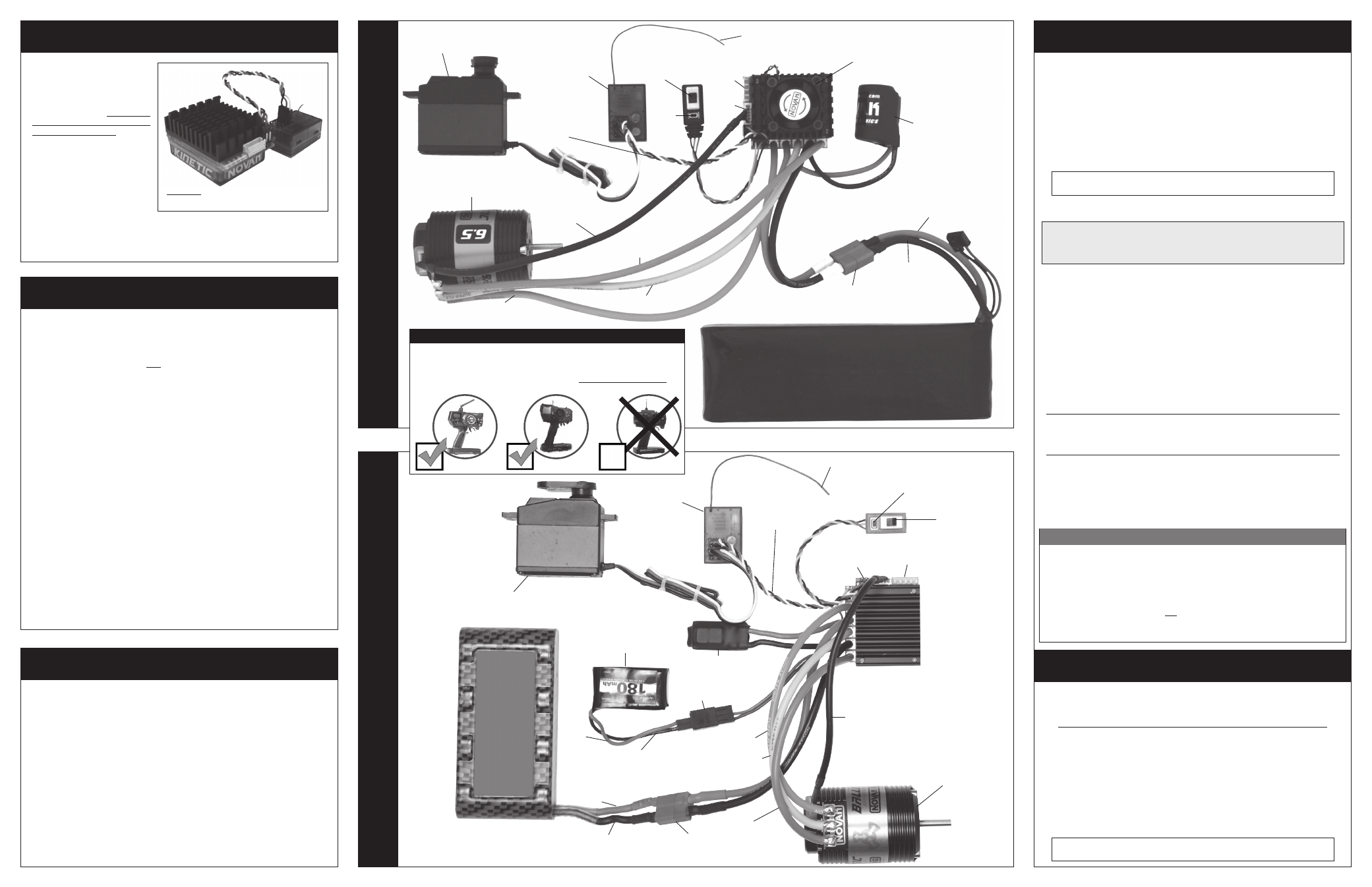
KINETIC 1S
SET
-UP PHOTO
(FIGURE 3)
KINETIC 2S
SET
-UP PHOTO
(FIGURE 2)
Blue motor phase wires
(Phase A)
ESC
ON/OFF
Switch
User-replaceable
input signal harness
(Ch.2)
Servo plugged into
steering ch. (#1)
P2
Novak
sensor-based
brushless motor
(540-size)
Set
button
Status
LEDs
Power
output
pins
A
Red power wire
(battery positive)
Servo plugged into
steering ch. (#1)
Yellow motor phase wires
(Phase B)
User-replaceable
input signal
harness
(Ch.2)
Black power wire
(battery negative)
Trail excess wire off top
of antenna mast
Set
button
Status
LEDs
Power
output
pins
step 3–KINETIC 1S RECEIVER PACK
1–cell LiPo batter
y pack
bRUSHLESS mOtOr precautions
Cooling fan recommended
for 2S LiPo/LiFe and
6-cell NiMH/NiCd use
(refer to Fig. 4)
1S Power Trans-
Cap Module
(Novak #5687)
FM Receiver
ESC
ON/OFF
Switch
battery
connector
B
FM Receiver
Trail excess wire off top
of antenna mast
sensor
harness
Orange motor
phase wires
(Phase C)
C
External 2S LiPo
receiver pack
(not included)
Novak sensor-based brushless motor
(540 or 550-size)
Blue motor
phase wires
(Phase A)
Yellow motor phase wires
(Phase B)
Orange motor
phase wires
(Phase C)
sensor harness
A
B
C
Red power wire
(battery positive)
Black power wire
(battery negative)
battery
connector
2S Power
Trans-Cap
Module
(Novak #5679)
step 5–Wire ESC to Battery
receiver pack
connector
If using a Kinetic 2S (Novak #1740), skip to Step 4.
The Kinetic 1S speed control is wired for using an external 2S LiPo receiver
battery pack to power the vehicle’s electronics. This method provides the
best possible performance and prevents the radio system from cutting-out.
The electronics cut-out because of excessive spikes of current being drawn
by the motor when the voltage of the battery pack has dropped during
the run, allowing the voltage to drop below the required level of the radio
system. The best solution to this problem is to power the vehicle’s radio
system and electronics from a separate power source than what is being
used to supply power to the motor. Because of the power requirements
of 2.4GHz radio systems, we have designed this system to use a 2S LiPo
receiver battery pack for adequate voltage headroom.
1. INSTALL EXTERNAL 2S LiPo RECEIVER PACK
(Refer to Fig. 3)
Plug a fully charged external 2S LiPo receiver battery pack into the speed
control’s receiver pack connector. Be sure to match the red wire from
the battery pack to the red wire of the ESC, and the black wire of the
battery pack to the black wire of the ESC.
Battery pack
(2S LiPo/LiFe or 4-6 cell NiMH/NiCd)
Battery pack, servo, receiver, motor plugs, and external receiver pack (for Kinetic 1S Set-Up
Photo) are not included; items are available separately.
Red
power
wire
(battery
positive)
Black power wire
(battery negative)
With the higher performance of brushless systems, undesirable radio system
noise may occur when used with lower quality radio systems. 2.4GHz radio
systems are the best to use. FM radio systems are acceptable, as long as
the system is high quality. AM radio systems are NOT recommended.
Best to use
2.4 GHz
OK to use
FM
Do not use
AM
GOOD QUALITY RADIO SYSTEM SUGGESTED
FIGURE 1
Input harness plugged into Ch. 2 of the receiver.