Traxxas e-maxx recommended inst alla tion, Sensor harness wiring, Novak electronics, inc – Novak HV Pro ESC (with purple heat sinks) Programming and Gearing (55-3410-1) User Manual
Page 2: Hook-up instructions motor maintenance, Accessories, E-maxx upgrades, Service procedures, Product warranty
P3
P2
TRAXXAS E-MAXX RECOMMENDED INST
ALLA
TION
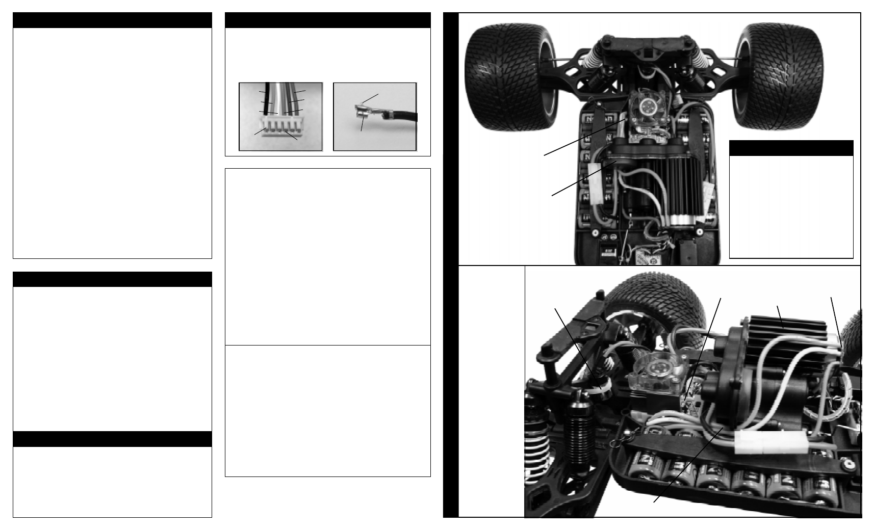
For installation in the T
raxxas E-Maxx, we recommend installing the HV
-Maxx in
the stock speed control mounting position with the front of the ESC facing the
pinion/spur gear cover--this way the cover can still be removed without removing
the speed control from the vehicle. The HV
-Maxx system comes ready to install
in the E-Maxx--the motor heat sink is aligned for installing the motor on the left
side of the vehicle as shown here. The included #4x1” self-tapping screws will
go through the fan bracket, the ESC’
s mounting ears, and thread directly into
the E-Maxx’
s stock ESC mounting holes in the chassis.
HV brushless
motor mounted
in left-hand
motor position
Direct-Solder
PCB wire tabs for
phase/power
wires on motor
HV-Maxx with
cooling fan
mounted in stock
ESC location
#4x1” self-tapping
screws into stock
mounting holes
Motor hole cover
screwed in place of
2nd motor to keep
debris out of gears
& slipper
SENSOR HARNESS WIRING
Should any of the 26G Teflon wires pull out of the connector on
the motor’s sensor harness, re-insert them in the appropriate slot
in the connector as shown below. There is a small plastic tab
that grabs a small raised barb on the back of the metal socket
crimped to the Teflon wire’s end. The plastic tab should be
checked to make sure it has not deformed excessively before
inserting the socket into the plastic connector housing.
black
orange
white
plastic
tabs
red
blue
green
metal
barbs
raised
metal
barb
metal socket
on end of Teflon
sensor harness wires
SERVICE PROCEDURES
Review instructions before sending motor for service--motor may
appear to have failed when other problems exist.
After reviewing the instructions, if you feel the motor requires
service, please obtain the most current product service options
and pricing by one of the following methods:
WEBSITE: Print a copy of the product SERVICE FORM from the
SERVICE section of Novak website. Fill out the needed information
and return it with the Novak product.
PHONE/FAX/E-MAIL: Contact our customer service department
by phone, fax, or e-mail (see CUSTOMER SERVICE section below),
and they will supply you with current service options.
WARRANTY SERVICE: For warranty work, you MUST CLAIM
WARRANTY on the product SERVICE FORM and include a valid,
itemized cash register receipt with purchase date and dealer name
& phone number on it, or an invoice from previous service work.
If warranty provisions have been voided, there will be service charges.
ADDITIONAL NOTES:
• Brushless ESC & Motor should be returned together.
• Hobby dealers or distributors are not authorized to replace
Novak products thought to be defective.
• If a hobby dealer returns your product for service, submit a
completed product SERVICE FORM to the dealer and make sure
it is included with the items.
PRODUCT WARRANTY
Novak brushless motors are guaranteed to be free from defects in materials or
workmanship for a period of 120 days from the original date of purchase (verified
by dated, itemized sales receipt). Warranty does not cover incorrect installation,
components worn by use, cross-connection of battery/motor power wires, over-
heating PCB solder tabs, damage resulting from thermal overload, splices to
sensor harness, damage from disassembling motor, over-tightening or using too
long of motor mounting screws, tampering with internal electronics, allowing water,
moisture, or any other foreign material to enter motor or get onto the PC board,
allowing exposed wiring or solder tabs to short-circuit, or any damage caused by
a crash, flooding, or act of God. In no case shall our liability exceed the product's
original cost. We reserve the right to modify warranty provisions without notice.
Because Novak Electronics, Inc. has no control over the connection and use of the
motor or other related electronics, no liability may be assumed nor will be accepted
for damage resulting from the use of this product. Every motor is thoroughly tested
and cycled before leaving our facility and is, therefore, considered operational. By
the act of connecting/operating speed control, the user accepts all resulting liability.
©2004 Novak Electronics, Inc. • All Rights Reserved • No part of these
instructions may be reproduced without the written permission of Novak
Electronics, Inc. • All Novak motors are designed & assembled in the U.S.A.
Novak Electronics, Inc.
(949) 833-8873 • FAX (949) 833-1631
M-Th: 8am-5pm
(PST)
• Fr: 8am-4pm
(closed every other Friday)
e-mail: [email protected] • web:
www.teamnovak.com
1. MOTOR CAPACITORS & SCHOTTKY NOT NEEDED
Novak brushless motors have built-in motor capacitors, and
like all reversible ESCs, do not use external Schottky diodes.
Schottky diodes damage reversible ESCs & void warranty.
2. CHECK MOTOR SCREW LENGTH
Insert the M3 motor mounting screws that came with your
vehicle through the motor mounting plate in vehicle. You
need to have no more than 1/8” of screw extending past
the vehicle’s mounting plate (2-4mm). Too little can strip
the threads in the end bell, and any more will cause short-
circuiting/damage inside the motor & will void warranty.
3. INSTALL PINION GEAR (see GEAR SELECTION on back)
Install pinion gear on motor and position set-screw over flat
on end of shaft. Test fit motor in vehicle to align pinion and
spur gears, then tighten pinion gear on shaft.
4. INSTALL MOTOR IN VEHICLE
• Determine the best routing for sensor harness & motor
power wire. Some off-road cars may require unsoldering
motor to route wires through the shock tower--refer to the
“WIRING MOTOR TO ESC” section.
• Using the M3 motor screws that came with your vehicle,
attach motor to vehicle’s motor mount using one of the
three sets of threaded mounting holes--
select a mounting
position that will avoid short-circuiting of solder tabs on
conductive surfaces such as aluminum or graphite.
• Check gear mesh for proper amount of play. You want to
have a small amount of free play between the pinion and
spur gears (about the thickness of piece of paper)--check
free play at several positions around the spur gear.
• Avoid using excessive force when tightening motor screws,
as the threaded holes could become stripped.
HOOK-UP INSTRUCTIONS
MOTOR MAINTENANCE
• CHECK MOTOR SCREWS Check all motor screws for
loosening at regular intervals, just like other hardware on your
vehicle. Note: The 3 main 4-40 socket head screws on the
shaft end of the motor may become loose after a few runs of
the motor and will need to be tightened. Also check the 3 flat
head screws securing the end cap on the back of the motor.
• CHECK MOTOR BEARING WEAR After extensive use, the
ball bearings in the end bells of your brushless motor may
need to be replaced. While the design of the motor will keep
the majority of debris out of the bearings, some debris may get
in, and eventually wear will occur. If the shaft will not spin freely,
you may need to replace the bearings (replacement bearing sets
are available in Novak accessory kit #5910 and include bearing
replacement instructions--If you do not feel comfortable changing
the bearing on your own, please contact our Customer Service
Dept. for assistance). A small drop of light oil on the bearings
periodically can help extend bearing life--too much oil will cause
problems, so apply sparingly.
SUPER-FLEX SILICONE POWER WIRE
Novak Super-Flex wire for power wiring. 14 gauge silicone wire in
kit #5500 (36”red/36”black), and 12 gauge silicone in kit #5530
(36”red/36”black).
H-SERIES MOTOR END BELL & BEARING SET
After extensive use, the ball bearings in the end bells of your
brushless motor may need to be replaced. Replacement front end
bell with oversize bearing factory-installed & rear bearing are available
in Novak kit #5910.
ACCESSORIES
Power Capacitor
tie-wrapped to “X”
in shock tower
Motor power wires routed through wire
holds in gear cover & in gap under cover
E-MAXX UPGRADES
After extensive testing, we’ve found the
high-power output from the HV-Maxx
system to be too much for the stock
E-Maxx components. We recommend
the following performance upgrades:
Front & Rear CVDs
&
CVD out drives
(we used MIP CVDs & outdrives)
Heavy-duty slipper w/spur gear
(we used Robinson’s slipper & 70T spur)
Metal transmission idler gears
*Check our website for more information