Step, Connect input harness, Motor installation – Novak HV Motor Wiring & Gear Selection (55-3020-1) User Manual
Page 2: Battery connection, Mounting esc, Figure 4: set-up photo, Sensor harness wiring
The HV-Maxx ESC has the industry-standard receiver input connector on a
user-replaceable input harness & works with all major radio brand’s new
receivers. However, some very old receivers must have the wiring sequence
in the plastic 3-pin connector housing changed. This is important, because
receiver & servo electronics may be damaged if the sequence is incorrect.
JR • Hitec • Futaba • New KO • Airtronics Z
JR • Hitec • Futaba • New KO • Airtronics Z
JR, Hitec, Futaba, new KO, & Airtronics Z receivers do not need input
harness re-wiring. Airtronics Z receivers have blue plastic cases & new KO
cases have tabs on the input harness openings as in Figure 1.
• Plug the connector on one end of the input harness into the receiver with
the BLACK wire toward the outside edge of receiver case.
• Plug the other end of the input harness into 3-pin header inside rectangular
opening on top of the HV-Maxx ESC’s case with the WHITE wire toward
the ‘S’ (signal) marking on the ESC’s label.
Old-style KO • Old-style Sanwa/Airtronics
Old-style KO • Old-style Sanwa/Airtronics
If you have an older KO or Sanwa/Airtronics, you must change the
sequence of the ESC’s input harness wires--Old Sanwa/Airtronics cases
are black color & Old KO cases do not have tab openings, as in Figure 2 above.
• Using a small flat blade screwdriver, remove the red & black wires from the
plastic housing at the receiver end of the input harness as in Figure 3 below.
• Interchange the red and black wires in the plastic 3-pin connector housing
at the receiver end of the input harness.
• Insert modified end of the harness into the receiver with the RED wire
toward the outside edge of receiver case.
FIGURE 3
With a small standard screwdriver, gently lift plastic
prong until wire and metal socket easily slide out of plastic housing.
changing wiring sequence
changing wiring sequence
changing wiring sequence
changing wiring sequence
changing wiring sequence
@
@
@
@
@
receiver end
receiver end
receiver end
receiver end
receiver end
FIGURE 1
FIGURE 2
New KO (with tabs)
Old KO (no tabs)
tabs
no tabs
black
red
red
white
black
white
P2
P3
step
step
step
step
step
1
11
1
1
–
connect input harness
step
step
step
step
step
3
3
3
3
3
–
motor installation
1. MOTOR CAPACITORS NOT NEEDED
Novak brushless motors have built-in motor capacitors and do not
require external ones on the motor
(see separate Motor Sheet for more info)
.
2. DO NOT USE SCHOTTKY DIODES
Schottky diodes must NOT be used with reversible speed controls
(including brushless). Using a Schottky diode will damage the speed
control and void the product’s warranty.
3. FACTORY-INSTALLED POWER CAPACITOR
MOUNTING THE POWER CAPACITOR:
Mount the Power Capacitor
to the vehicle’s chassis using the included double-sided tape or with
tie-wraps
[in Traxxas E-Maxx: You can tie-wrap the power capacitor to
the “X” in the middle of the rear shock tower].
If Power Cap. becomes dented or damaged, ESC failure can occur--replace
immediately. Longer Power Capacitor wires decrease performance.
4. CHECK MOTOR SCREW LENGTH
You must check the length of the motor screw to ensure that the motor
will not be damaged. You should have no more than 1/8” of screw
extending past the vehicle’s motor mounting plate (2-4mm). Too little
can strip the threads in the end bell, and any more will cause damage
& short-circuiting inside the motor & will void warranty.
[the included
M3x8mm screws are the proper length for the Traxxas E-Maxx]
5. INSTALL PINION GEAR
{
refer to ‘GEAR SELECTION’ portion of MOTOR
}
SET-UP sheet to determine the proper gearing
After selecting the proper final gear ratio, install pinion gear (usually
about 2 teeth smaller than stock) on motor and position set-screw over
the flat on the end of the motor shaft. Test fit motor in vehicle to align
pinion and spur gears, then tighten pinion gear on shaft.
6. USE SPIRAL WRAP TO BUNDLE/PROTECT SENSOR WIRES
Use the spiral wrap included in the HV-Maxx’s accessory kit to protect
the 6 Teflon sensor harness wires between the ESC & the motor. You
can also use the spiral wrap and tie-wraps to bundle the sensor harness
& motor power wires neatly together.
step
step
step
step
step
4
4
4
4
4
–
battery CONNECTION
The HV-Maxx is very powerful, and capable of very efficient delivery of
battery power to its brushless motor. Therefore, good connections must
be made between the battery, speed control, and motor.
A common cause of perfomance problems and ESC failures is poor
connections--If you have any doubts about your soldering skill, we suggest
installing the system without modifying the length of the power wires,
or seeking assistance at your hobby shop or track.
Once you’ve mounted the HV-Maxx ESC & motor, it’s time for the bat-
tery connections. The HV-Maxx ESC is factory-wired for two battery
packs, and is equipped with high-power versions of JST/Tamiya-style
battery connectors so you can use standard sport battery packs.
Using different style connectors is discussed on the Motor Sheet.
BATTERY PACK CONNECTIONS
The HV-Maxx system is designed to be used with two battery packs.
However, it can also be used with one standard R/C battery pack (6 or 7
cells @ 1.2VDC/cell) or with one 12 volt DC battery. Using the HV-Maxx
with a single battery requires special wiring and is discussed below.
using dual battery pack
using dual battery packs
s
::
a.
a.
a.
a.
a.
Connect one battery pack (6-7 cells @ 1.2VDC/cell) to the JST/Tamiya
connector at the end of the red & black wires coming from the
ESC’s BAT.1 solder tabs as marked on the HV-Maxx case labels.
b.
b.
b.
b.
b.
Connect a second battery pack to the JST/Tamiya connector coming
from the ESC’s BAT.2 solder tabs.
using single battery pac
using single battery pack
k
::
To use the HV-Maxx with a single 6-14 cell (1.2VDC/cell) pack or a
12VDC battery, the pack/battery must be connected to the BAT.2
input & the BAT.1 input must be shorted together
(see Fig.7 below/left)
.
a.
a.
a.
a.
a.
Cut the black wire coming from the BAT.1 (–) solder tab (battery
wire closest to the front of ESC) about 2-3” above the solder tab.
b.
b.
b.
b.
b.
Strip a 1/8-1/4” of insulation off the end of the BAT.1 (–) black
wire. Tightly twist the strands of wire & lightly tin with solder.
CAUTION: When making battery wire solder connections at the
HV-Maxx’s Direct-Solder Wiring Tabs, it is important to not overheat
& damage PCB (printed ciruit board) with the soldering iron by applying
prolonged or excessive heating (PCB damage voids warranty).
c.
c.
c.
c.
c.
Remove the red wire from the BAT.1 (+) solder tab:
Use a soldering iron to apply heat to the wire’s solder joint while
gently pulling on the wire to remove it from the PC Board’s hole.
d.
d.
d.
d.
d.
Solder the stripped & tinned end of the black wire coming from the
ESC’s BAT.1 (–) solder tab into the BAT.1 (+) solder tab:
Insert the wire end into the BAT.1 (+) solder tab hole (if there is still
solder in the hole you can melt it with the iron while pushing the wire
through the hole). Apply heat to the section of wire that is sticking
through the tab’s hole, and add solder to the tip of the soldering
iron and to the wire. Add just enough solder to form a clean &
continuous joint from the plated area of the solder tab up onto the
wire. Use side cutters to trim excess wire above tab (about 1/16”).
e.
e.
e.
e.
e.
Connect battery pack (6-14 cells @ 1.2VDC/cell) to the JST/Tamiya
connector at the end of the red & black wires coming from the
ESC’s BAT.2 solder tabs as marked on the HV-Maxx case labels.
B.E.C. OUTPUT WHEN USING SINGLE BATTERY ABOVE 8.4VDC
When using a single battery above 8.4VDC (like a lead acid or gell cell), there
is limited output from the B.E.C. circuit--using a separate receiver battery
pack (refer to Motor/Wiring Sheet) can improve servo/receiver performance.
Important motor, gear selection, & wiring information on separate Motor/Wiring Sheet
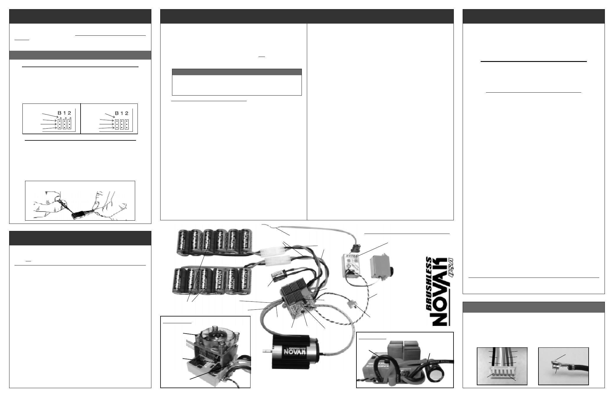
sensor harness wiring
sensor harness wiring
sensor harness wiring
sensor harness wiring
sensor harness wiring
Should any of the 26G Teflon wires pull out of the connector on the motor’s
sensor harness, re-insert them in the appropriate slot in the connector as
shown below. There is a small plastic tab that grabs a small raised barb on
the back of the metal socket crimped to the Teflon wire’s end. The plastic
tab should be checked to make sure it has not deformed excessively before
inserting the socket into the plastic connector housing.
If the sensor harness gets damaged, contact our Customer Service Department.
step
step
step
step
step
2
2
2
2
2
–
MOUNTiNG ESC
Mount ESC with power wires away from other electronics & moving parts.
Select a location that allows airflow through heat sinks--
If the ESC gets air
flow, it will run cooler; and that means it will be more efficient, and you will go faster!
For single battery pack use, proceed to STEP 4 before completing STEPs 2 & 3
1. MOUNT HV-MAXX ESC IN VEHICLE using the included double-sided
tape or with screws through the mounting ears on the sides of the case
[in Traxxas E-Maxx: If using cooling fan, install with the included #4x1”
self-tapping screws--If not using cooling fan, use the stock mounting
screws from the original ESC in the E-Maxx].
2. PLUG COOLING FAN INTO ESC’s FAN POWER OUTPUT JACK Remove
rubber plug from ESC’s fan power output jack located directly above the
input signal harness opening (see Fig.5 below/right) & pull it back out of the
way. Plug fan connector into the power output jack (Note polarity: RED =
+
).
3. INSTALL FAN BRACKET ONTO ESC using included #6x5/8” self-tapping
screws
[in Traxxas E-Maxx: The #4x1” self-tapping screws will be used & will
pass through the cooling fan bracket, then the ESC’s mounting ears, & into
the holes in the E-Maxx’s chassis]
. Position fan bracket on ESC so that the
holes for attaching the fan to the bracket are towards the front of ESC.
4. INSTALL COOLING FAN ONTO BRACKET using the included 4-40x1/2”
socket head screws. Position fan so it is directly over the ESC’s heat sinks
and thread screws into the 2 holes on the top of the fan mounting bracket.
5. INSTALL ESC ON/OFF SWITCH using a screw or double-sided tape where
it will be easy to access
[in Traxxas E-Maxx: You can screw the switch to
one of the holes from the original switch]
.
6. CONNECT ESC TO RECEIVER––Configure input harness wires as
described in Step 1 & connect ESC to the THROTTLE CHANNEL (#2) of
receiver. Be sure receiver & antenna are mounted as far from ESC, power
wires, battery, and servo as possible--these components all emit RF noise
when throttle is applied.
On graphite or aluminum chassis vehicles, it may help
to place receiver on edge with crystal & antenna as far above chassis as possible.
Note: Mount antenna as close to receiver as possible--trail any excess wire off top
of antenna mast (cutting or coiling excess antenna wire will reduce radio range).
Motor Installation: continued –>
why you want a power capacitor
why you want a power capacitor
why you want a power capacitor
why you want a power capacitor
why you want a power capacitor
The HV-Maxx comes with the best available Power Capacitor that drops ESC operating
temperatures by 10-15
°
F (remember, cooler means your ESC will be more efficient &
faster) and dissipates noise & voltage spikes from the ESC’s high switching speed.
You MUST use Novak Power Capacitors--other capacitors with similar ratings don’t provide
equal protection. We’ve done extensive research to find capacitors with the very best quality factors.
continued I
^
7. INSTALL MOTOR IN VEHICLE
For most applications, the HV-Maxx ESC & brushless motor can be
installed in the vehicle without any modification to the motor wiring.
• Determine the best routing for the motor’s sensor harness (6 small Teflon
wires).
[in Traxxas E-Maxx: Both the sensor harness & the ESC’s input
signal harness can be routed through the gap located beneath the
pinion/spur gear cover on the left side of the vehicle--between the
transmission case & the battery box wall].
• Attach motor to the vehicle’s motor mount with included M3 motor
screws (determine proper length motor screws in Step 3, #4), using one of
the three sets of threaded mounting holes in the front end bell--select
a mounting position that will avoid short-circuiting of motor’s solder tabs
against conductive surfaces like aluminum or graphite.
The HV motor included in the HV-Maxx brushless motor system comes
with a heat sink factory-installed on it for extra cooling under excessive
loads
[for the Traxxas E-Maxx: The heat sink is already pre-positioned
on the motor for installation on the left hand side of the E-Maxx--
install motor with the solder tabs toward the middle of the vehicle &
angled slightly upward].
You can rotate the heat sink on the motor as
needed for different applications--beware of any wires crossing the
sharp ends of the heat sink, as short-circuiting may occur.
• Check gear mesh for proper free play. You want to have a small amount
of play between the pinion & spur gears (about the thickness of a piece
of paper)--check free play at several positions around the spur gear.
• Tighten motor into position once desired gear mesh has been adjusted-
-avoid using excessive force when tightening motor screws, as the
threaded holes could become stripped.
• For vehicles that originally used 2 motors, use the included motor
hole cover in place of the 2nd motor (this will help keep debris out of
the slipper and the gears). Install motor hole cover using the vehicle’s
original motor screws or with two 4-40x1/4” screws.
• Replace any parts of the vehicle that were removed to install the motor.
[in Traxxas E-Maxx: Replace the pinion/spur gear cover]
.
• Determine best routing for the motor’s power wires. If your vehicle
requires unsoldering motor to route power wires through the
shock tower or chassis, refer to “REPLACING POWER WIRES AT ESC &
MOTOR” on Motor Sheet.
[in Traxxas E-Maxx: Route motor power wires
along the right side of transmission--2 wires press into the wire holds on
the lower side of pinion/spur gear cover, & the 3rd wire goes through
the gap between the transmission case & the battery box wall].
black
orange
white
plastic
tabs
red
blue
green
metal
barbs
raised
metal
barb
metal socket
on end of Teflon
sensor harness wires
FIGURE 5:
Cooling fan connection
fan plugs
into fan power
output jack
self-tapping screws
into ESC mounting
ears or through ears
into chassis
4-40x1/2” cap
screws secure
fan to custom
bracket
Power Cap
taped or
tie-wrapped
to chassis
One-Touch
button
Keep receiver & antenna as
far from motor, servo,
battery, & power wires as
possible.
U
ser-replaceable
input harness
Black power wires
(battery negative)
Trail excess wire off
top of antenna mast
Red power wires
(battery positive)
Blue power wire
(motor phase ‘A’)
(–)
(+)
6 to 7 cell battery packs
Novak Platinum GP3300VE
shown (part #6000)
ON/OFF switch
screwed or taped to chassis
(–)
(+)
Yellow power wire
(motor phase ‘B’)
servo
plugged
into
ch. (#1)
Orange power wire
(motor phase ‘C’)
Status LEDs
Sensor
harness
input
Fan power
output jack
ESC screw
mounting ears
FIGURE 4: SET-UP PHOTO
FIGURE 6:
BAT.1 shorting for single battery usage
battery connects
to BAT.2 input
BAT.1(–) shorted
to BAT.1(+)