Custom programming options -- advanced, Minimum brake, Drag brake – Novak Havoc Pro Set-Up (55-1745P-1 Rev.4) User Manual
Page 2: Minimum drive, Timing level, Timing set point, Dead band, Throttle curve, Brake curve, Brake frequency
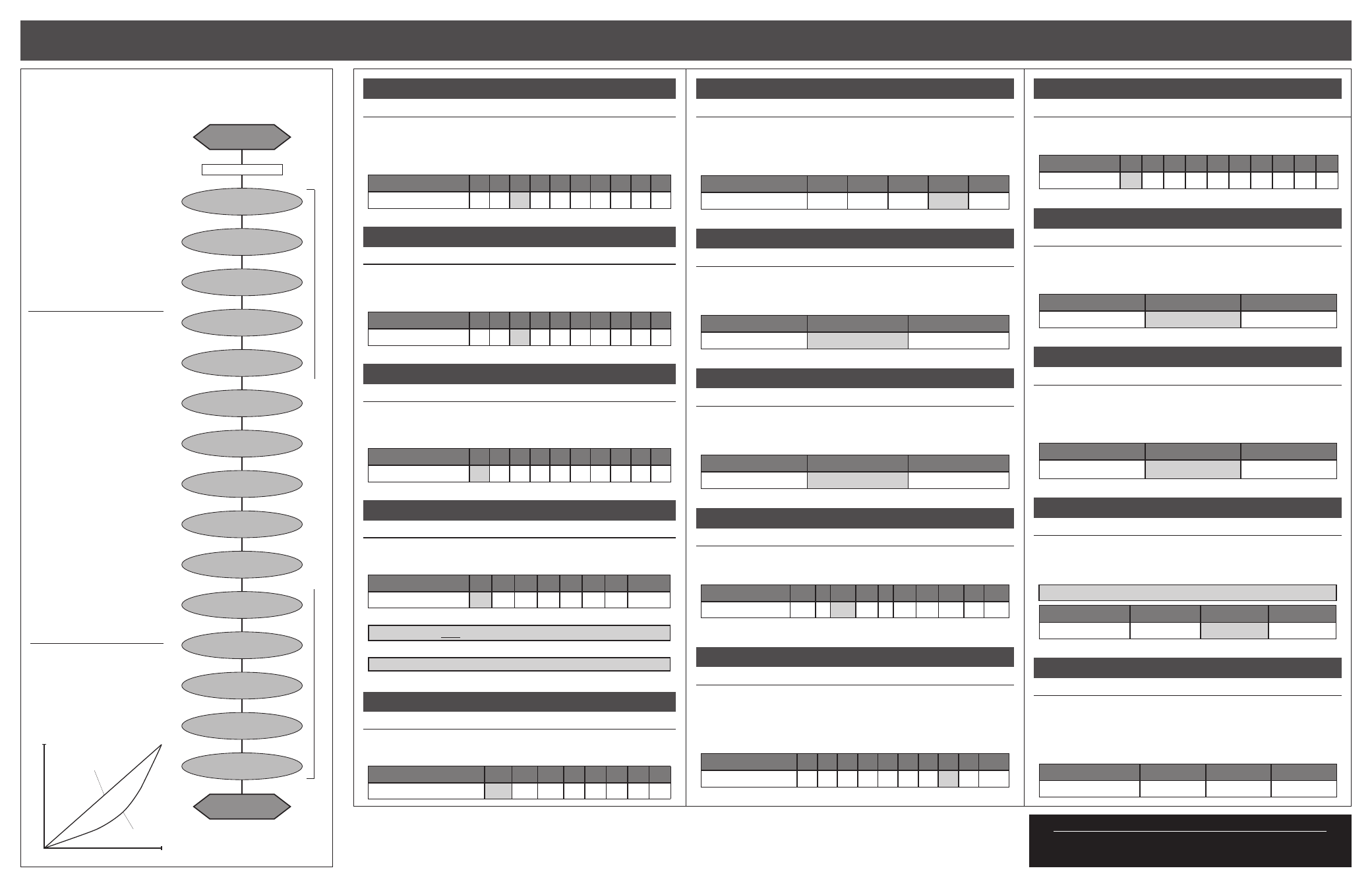
havoc pro sc software flow chart
CUSTOM programmiNG options -- advanced
P6
w w w . t e a m n o v a k . c o m
P7
The Havoc Pro SC ESC features over
a dozen parameters that can be
customized to fine-tune the ESC’s
feel & response to your liking.
The flow chart below and the
adjustment steps to the right
describe the different parameters
and how they effect the ESC.
One-Touch Programming must be
completed before customization of
parameters, as all ESC parameters
are defaulted back to the factory
settings whenever the One-Touch
Programming is performed.
DEFAULT SETTINGS FOR
THE ESC PARAMETERS ARE
LISTED IN BOLD IN THE
TABLES TO THE RIGHT
TO CHANGE PARAMETER SETTINGS:
1. CONNECT THE ESC TO A
CHARGED BATTERY PACK,
RECIEVER, AND MOTOR’S
SENSOR HARNESS
2. SLIDE THE ESC’s ON/OFF
SWITCH TO ‘ON’ POSITION
3. WITH ESC AT NEUTRAL, PRESS
& HOLD SET BUTTON
Release ESC’s SET button once LEDs
are lit for the desired setting.
To skip a parameter, continue
to press & hold SET button until
desired parameter is reached.
4. SELECT PARAMETER VALUE
LED flashes to indicate active
setting (refer to tables at right).
Quick press & release SET button
to select desired setting.
5. PRESS & HOLD SET BUTTON
TO STORE NEW SELECTION
When SET button is pressed and
held for about 1 second,
the
new selection is stored in ESC’s
memory—Status LEDs will scroll across
to indicate ESC is exiting programming
& ESC returns to neutral.
There is no time constraint during
selection of custom parameters.
THROTTLE and
brake CURVES
The Havoc Pro SC features both
linear and exponential throttle &
brake curves. The ‘Expo’ curves
provide a more controllable bottom
end response.
minimum brake
#1 MINIMUM BRAKE SETTINGS
(1 of 10)
BLUE LED
Amount of braking applied with the first pulse of transmitter throttle information sent.
>> Increasing this setting starts the braking at a stronger/higher
level. This is useful to compensate for heavier vehicles to minimize the
amount of trigger throw required before effective braking is applied.
Note: Blue LED will be ON when ESC is at neutral if this setting is above 0%.
Setting
(# of flashes)
1
2
3
4
5
6
7
8
9 10
Minimum Brake (%):
0
3
6
9 12 15 18 21 24 30
drag brake
#2 DRAG BRAKE SETTINGS
(1 of 10)
BLUE & YELLOW LEDs
Amount of braking being applied while transmitter is at neutral. AKA ‘coast’ brakes.
>> Increasing this setting makes the motor slow down more without
pushing the transmitter’s trigger into the brake/reverse direction.
Note: Yellow LED will be ON when ESC is at neutral if this setting is above 0%.
Setting
(# of flashes)
1
2
3
4
5
6
7
8
9 10
Drag Brake (%):
0
3
6
9 12 15 18 21 24 30
minimum drive
#3 MINIMUM DRIVE SETTINGS
(1 of 10)
YELLOW LED
Amount of forward drive applied with first pulse of transmitter throttle information sent.
>> Increasing this setting starts the forward drive at a stronger/higher
level. This is useful to compensate for heavier vehicles to minimize the
amount of trigger throw required before effective drive is applied.
Setting
(# of flashes)
1
2
3
4
5
6
7
8
9 10
Minimum Drive (%):
0
1
2
3
4
6
8 10 12 15
TIMING level
#4 TIMING LEVEL SETTINGS
(1 of 8)
GREEN-RED-WHITE LEDs
The maximum degrees of Dynamic Timing Advance applied to the motor.
>> Increasing this setting will increase the maximum amount of electronic
motor timing that is applied to the motor throughout the throttle band.
Setting
(# of flashes)
1
2
3
4
5
6*
7*
8*
Timing Level
(degrees):
0
20 25 30 32 35 37
42
Setting #1 disables all timing to meet ROAR’s Sportsman Class racing specs.
WARNING: DO NOT FREE-REV MOTOR TO CHECK TIMING SETTINGS
*Timing Levels 6-8 produce excessive heating & must be used with caution.
Physical motor timing should be set to 30° (“N” on older Ballistic motors)
Note: Do NOT use Timing Advance with 3.5-5.5 turn 540-Size motors.
TIMING SET POINT
#5 TIMING SET POINT
(1 of 8)
YELLOW-GREEN-RED-WHITE LEDs
The RPM trip point at which Dynamic Timing Advance is applied.
>> Increasing this setting will decrease the RPM at which the electronic
motor timing advancement comes on.
Setting
(# of flashes)
1
2
3
4
5
6
7
8
Timing Set Pt
(x1000 RPM)
:
19.5 14.0 12.7 9.1 6.5 5.5 4.5 4.0
Motor Output
Trigger Position
0
100%
Linear
Expo
100%
dead band
#6 DEAD BAND SETTINGS
(1 of 5)
BLUE & GREEN LEDs
The space between Minimum Brake and Minimum Drive, with Neutral in the middle.
>> Increasing this setting increases the amount of ‘free play’, or distance
your transmitter’s trigger must move before actual forward drive or
braking begins. This is useful for transmitters whose triggers do not
center accurately or have worn trigger pots.
Setting
(# of flashes)
1
2
3
4
5
Dead Band (%):
2
3
4
5
8
THROTTLE CURVE
#7 THROTTLE CURVE SELECTION
(1 of 2)
GREEN & WHITE LEDs
How the ESC’s throttle (or forward drive) responds to the transmitter’s trigger input.
>> Changing this setting changes how the throttle responds to your
transmitter’s trigger movement. The ‘Expo’ curve gives a less responsive,
or more forgiving low-end acceleration.
Setting
(# of flashes)
1
2
Throttle Curve:
Linear
Expo
BRAKE CURVE
#8 BRAKE CURVE SELECTION
(1 of 2)
RED & WHITE LEDs
How the ESC’s brakes respond to the transmitter’s trigger input.
>> Changing this setting changes how the brakes respond to your
transmitter’s trigger movement. The ‘Expo’ curve gives a less responsive,
or more forgiving low-end braking.
Setting
(# of flashes)
1
2
Brake Curve:
Linear
Expo
BRAKE FREQUENCY
#9 BRAKE FREQUENCY SELECTION
(1 of 10)
RED LED
How the ESC’s braking response feels with respect to the transmitter’s trigger input.
>> Increasing the Brake Frequency makes the brake response feel
smoother and more controlable.
Setting
(# of flashes)
1
2
3
4
5
6
7
8
9
10
Brake Freq. (KHz):
1.67 2 2.25 2.5 3 3.5 4.5 5.75 10 13.7
Note: Brake/Drive Frequency is not adjustable with Expo Brake/Drive Curves.
BRAKE END POINT
#10 BRAKE END PT. SELECTION
(1 of 10)
YELLOW-RED-WHITE LEDs
The percentage of the ESC’s braking power that can be attained as well as the
transmitter trigger throw required to reach that power.
>> Decreasing this setting reduces the maximum braking power and the
usable distance of the transmitter’s brake trigger throw. The ‘Linear’ or
‘Expo’ brake curves will be cut off at this point, and you will get that
percentage/level of braking for the rest of the transmitter’s trigger throw.
Setting
(# of flashes)
1
2
3
4
5
6
7
8
9
10
Brake End Pt. (%):
10 20 30 40 50 60 70 80 90 100
Note: At high timing settings, use 100% (setting 10) Brake End Point.
DRIVE FREQUENCY
#11 DRIVE FREQUENCY SELECTION
(1 of 10)
GREEN LED
How the ESC’s throttle response feels with respect to the transmitter’s trigger input.
>> Increasing the Drive Frequency makes the throttle response feel
smoother and more controllable.
Setting
(# of flashes)
1
2
3
4
5
6
7
8
9
10
Drive Freq.
(KHz)
:
32 27 24 22 21 16 13 10
8
6
reverse
#12 REVERSE SELECTION
(1 of 2)
YELLOW-GREEN-RED LEDs
>> Changing this setting activates or deactivates the speed control’s
motor reversing functionality. When OFF, the ESC has forward and
brakes only. When ON, the ESC has forward with brakes, then reverse
with a second push of trigger after braking to a slow speed.
Setting
(# of flashes)
1
2
Reverse:
OFF
ON
motor rotation
#13 MOTOR ROTATION SELECTION
(1 of 2) BLUE-GREEN-RED LEDs
>> Changing this setting changes the rotational direction of the motor’s
output/pinion shaft. Counter-clockwise rotation is standard in most
remote control vehicles. For optimal motor performance, use counter-
clockwise rotation instead of reversing the transmitter’s throttle
channel throw. Advanced timing is not available in clockwise rotation.
Setting
(# of flashes)
1
2
Rotation Direction:
CCW
Q
CW
P
voltage cut-off
#14 VOLTAGE CUT-OFF SELECTION
(1 of 3)
YELLOW & RED LEDs
>> Changing this setting enables or disables the speed control’s
built-in Smart Stop cut-off circuitry, and also sets the voltage cut-off
point based on what type of batteries are being used in the vehicle’s
main battery pack.
DO NOT USE LiPo/LiFe BATTERIES WITH VOLTAGE CUT-OFF TURNED OFF
Setting
(# of flashes)
1
2
3
Voltage Cut-Off Type:
OFF
(NiMH/NiCd)
LiPo
LiFe
hall sensor test
#15 MOTOR SENSOR TEST
BLUE-YELLOW-RED LEDs
>> This is a diagnostic feature that allows you to easily check the
functionality of your brushless motor’s hall effect sensors & sensor
harness and its connections at the speed control and motor. Once
activated, slowly rotate the motor’s output/pinion shaft and the
appropriate LED will light up if a signal is received for its sensor in
the motor. Refer to ‘MOTOR HALL SENSOR TEST’ section.
Motor Hall Sensor
A
B
C
LED Color:
BLUE
YELLOW
RED
restoring factory defaults
Every time that the One-Touch Programming is
performed, the speed control will automatically
revert back to the factory default settings.
Note: ESC Parameter values are subject to change due to ongoing development. Refer to our web site for updated values and more information on ESC parameters.
@NEUTRAL
RED LED on solid
MIN. BRAKE
BLUE
DRAG BRAKE
BLUE & YELLOW
DEAD BAND
BLUE & GREEN
MIN. DRIVE
YELLOW
press & hold SET button
continue holding ESC’
s SET button to skip steps here
TIMING LEVEL
GREEN-RED-WHITE
TIMING SET PT.
YELLOW-GREEN-RED-WHITE
THROTTLE CURVE
GREEN & WHITE
VOLTAGE CUT-OFF
YELLOW & RED
BRAKE CURVE
RED & WHITE
MOTOR ROTATION
BLUE-GREEN-RED
BRAKE FREQ.
RED
BRAKE END PT.
YELLOW-RED-WHITE
DRIVE FREQ.
GREEN
REVERSE
YELLOW-GREEN-RED
HALL SENSOR TEST
BLUE-YELLOW-RED
@NEUTRAL
RED LED on solid