Br u shl ess-m ode s et -up p h oto, Br u sh-m ode s et -up p h oto 2, S t e p – Novak Havoc Pro SC Basic Set-Up -- NEW (button on corner of PC board) (55-1733-1 Ver. 2) User Manual
Page 2: Step, One-touch programming
*If motor has no ground tab
(as shown here), solder the
capacitors to motor can.
The Havoc 3S ESC has the industry-standard receiver input connector on a user-
replaceable input harness & works with all major radio brand’s new receivers.
However, some very old receivers must have the wiring sequence in the plastic
3-pin connector housing changed. This is important, because receiver & servo
electronics may be damaged if the sequence is incorrect.
JR • Hitec • Futaba • New KO • Airtronics Z
JR, Hitec, Futaba, new KO, & Airtronics Z receivers do not need input
harness re-wiring. Airtronics Z receivers have blue plastic cases & new KO
cases have tabs on the input harness openings as in Figure 1.
• Plug one end of the input signal harness into the THROTTLE CHANNEL (#2)
of receiver with the BLACK wire toward the outside edge of receiver case.
• Plug the other end of the input harness into 3-pin header inside the ESC’s case
with the WHITE wire toward the ‘S’ (signal) marking on the ESC’s case above
the rectangular signal harness opening.
Old-style KO • Old-style Sanwa/Airtronics
If you have an older KO or Sanwa/Airtronics, you must change the sequence
of the ESC’s input harness wires—Old Sanwa/Airtronics cases are black color
& Old KO cases do not have tab openings, as in
Figure 2 above.
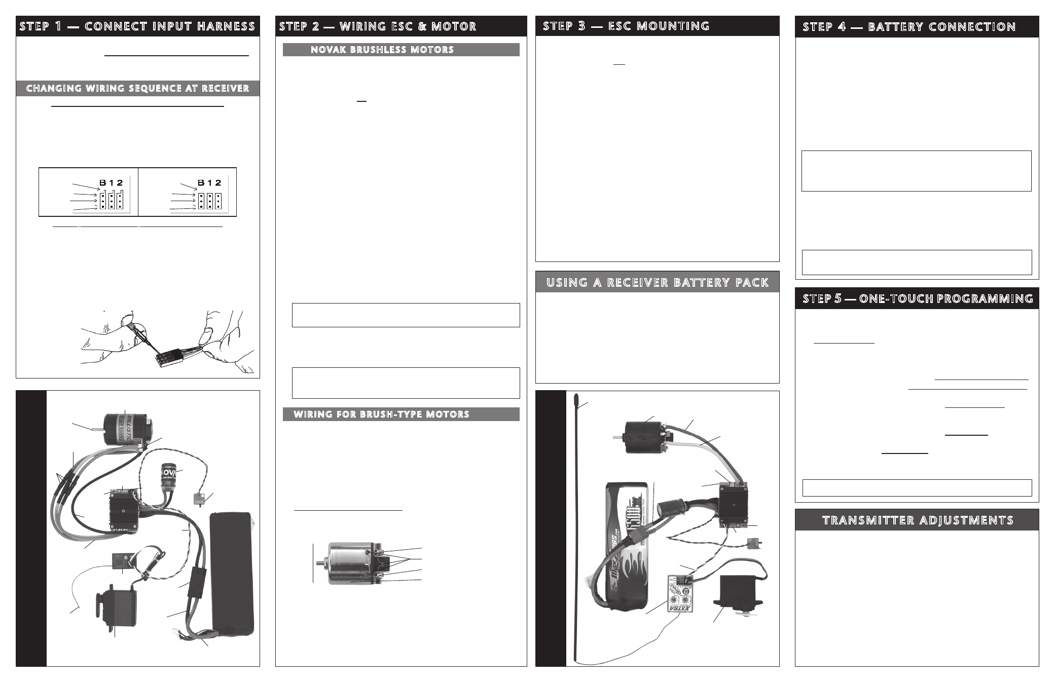
• Using a small flat blade screwdriver, remove the red & black wires from the plastic
housing at the receiver end of the input harness as in Figure 3 below.
• Interchange the red and black wires in the plastic 3-pin connector housing at
the receiver end of the input harness.
• Insert modified end of the harness into the THROTTLE CHANNEL (#2) of receiver
with the RED wire toward the outside edge of receiver case.
• Plug the other end of the input harness into the ESC with the WHITE wire toward
the ‘S’ (signal) marking on the ESC’s case.
FIGURE 3
With a small flat-
bladed standard
screwdriver,
gently lift plastic
prong until wire
and metal socket
easily slide out of
plastic housing.
c H a n G i n G W i R i n G S e q u e n c e at R e c e i V e R
FIGURE 1
FIGURE 2
New KO (with tabs)
Old KO (no tabs)
tabs
no tabs
black
red
red
white
black
white
S t e p
1
— c o n n e c t i n p u t H a R n e S S
1. MOTOR CAPACITORS NOT NEEDED
Novak brushless motors do not require external motor capacitors.
2. DO NOT USE SCHOTTKY DIODES WITH HAVOC 3S ESC
Schottky diodes must NOT be used with reversible ESCs (including brushless).
Schottky diode usage will damage the ESC & void warranty.
3. FACTORY-INSTALLED POWER TRANS-CAP MODULE REQUIRED
The factory-installed Power Trans-Cap module MUST be used with brushless
& brush-type motors. If Trans-Cap module becomes dented or damaged, ESC
failure can occur--replace immediately. Longer Trans-Cap module wires will
decrease performance.
4. CHECK FOR PROPER GEARING
Refer to the ‘PROPER GEAR SELECTION’ portion of the PROGRAMMING/
GEARING Sheet (Pg.5) to determine proper gearing & avoid overheating.
5. SOLDER MOTOR POWER WIRES TO MOTOR
*Skip this step if installing complete system with ESC factory-wired to motor.
A. Cut the BLUE, YELLOW & ORANGE silicone motor power wires to the
desired length, and strip 1/8-3/16” of insulation from the end of each wire.
Tightly twist the exposed strands of wire, and tin the exposed end section
of each wire with solder using a good, high heat iron.
B. Solder the ESC’s BLUE Phase ‘A’ motor wire to the motor’s phase ‘A’
solder tab. Apply heat to exposed wire with soldering iron, and add solder
to the tip of the iron & the wire—Add just enough solder to form a clean &
continuous joint from the solder tab up onto the wire.
IMPORTANT NOTE: DO NOT OVERHEAT SOLDER TABS
Prolonged/excessive heating of solder tabs (motor or ESC) will cause damage.
C. Solder the ESC’s YELLOW Phase ‘B’ motor wire to the motor’s phase ‘B’
solder tab as described in Step 5B above.
D. Solder the ESC’s ORANGE Phase ‘C’ motor wire to the motor’s phase ‘C’
solder tab as described in Step 5B above.
Note: Make sure no wire strands have strayed to an adjacent solder
tab, this will result in short-circuiting & severe ESC damage, which
will void the warranty.
6. CONNECT MOTOR’S SENSOR HARNESS TO ESC
Insert the 6-pin connector on the end of the motor’s sensor wires into ESC’s sensor
harness socket--the connector is keyed and will only go together in one direction.
7. INSTALL PINION GEAR (refer to Proper Gear Selection on p.5)
Note: When wiring the vehicle’s electronics, short wires & clean/neat
installations will give you better performance, higher efficiency & less
radio problems (glitching, etc.). Try your best to keep power wires
away from signal wires & receiver/antenna.
S t e p
3
— e S c M o u n t i n G
Mount ESC with power wires away from other electronics & moving
parts. Select a location that allows airflow through heat sinks—If the
ESC gets air flow, it will run cooler; and that means it will be more
efficient, and you will go faster!
1. MOUNT SPEED CONTROL IN VEHICLE
Use the included double-sided tape to mount ESC in vehicle (do not glue).
Avoid contact with side walls or other components to minimize vibration.
Be sure receiver & antenna are mounted as far from ESC, power
wires, battery, & servo as possible--these components all emit RF
noise when throttle is applied. On graphite or aluminum chassis
vehicles, it may help to place receiver on edge with crystal & antenna
as far above chassis as possible.
Note: Mount antenna as close to receiver as possible--trail
any excess wire off top of antenna mast (cutting or coiling
excess antenna wire will reduce radio range).
Do not wrap signal wires around power wires.
2. SECURE POWER TRANS-CAP MODULE TO CHASSIS
Use included double-sided tape, or a tie-wrap, to mount Trans-Cap
module to the vehicle’s chassis or shock tower. Trans-Cap module can
also be tie-wrapped along the power wires—this requires less space on
the chassis and provides good vibration isolation.
3. INSTALL ON/OFF SWITCH
Use a screw or the included double-sided tape, and mount the switch
where it will be easy to access—be sure to select a position where it will
not get damaged or get switched OFF during a crash or roll-over.
n o Va k B R u S H L e S S M o t o R S
(Figure 4)
W i R i n G f o R B R u S H - t Y p e M o t o R S
(Figure 6)
1. DISCONNECT BRUSHLESS MOTOR SENSOR HARNESS
The Havoc 3S ESC automatically switches to Brush-Mode when the ESC power
is switched ON and no brushless sensor harness is connected.
2. INSTALL MOTOR CAPACITORS
Electric brush-type motors generate RF noise that causes interference. Three
0.1µF (50V) non-polarized, ceramic capacitors must be used on all motors to
reduce motor noise & prevent ESC damage.
Note: Some motors come with built-in capacitors. If your motor only has 2 capacitors,
you need to install a capacitor between the positive & negative motor tabs––If you
experience radio interference with built-in capacitors only, install external ones.
Solder 0.1µF (50V) capacitors between:
• POSITIVE (+) & NEGATIVE (–) motor tabs.
• POSITIVE (+) motor tab & GROUND tab*.
• NEGATIVE (–) motor tab & GROUND tab*.
Negative (–) motor tab
0.1µF Capacitors
Positive (+) motor tab
Ground / motor can
3. SOLDER MOTOR POWER WIRES TO MOTOR
With brush-type motors, the Havoc 3S ESC’s BLUE and YELLOW wires must
be connected to the motor. It is recommended to use Novak’s 3.5mm Low-Loss
Power Connectors (#5730-5733) for a strong connection.
A. The ORANGE wire is unused with brush-type motors. It can be either de-
soldered from the ESC’s PCB, or heat shrinked and zip tied to prevent shorting.
B. Connect the BLUE ESC wire to the NEGATIVE (–) Motor Tab.
C. Connect the YELLOW ESC wire to the POSITIVE (+) Motor Tab.
4. INSTALL PINION GEAR (refer to Proper Gear Selection on p.5)
P2
S t e p 2 — W i R i n G e S c & M o t o R
With ESC connected to (at least) a receiver & a charged battery pack:
1. TURN ON THE TRANSMITTER’S POWER
2. PRESS & HOLD ESC’S ONE-TOUCH/SET BUTTON
3. TURN ON THE SPEED CONTROL’S POWER
With transmitter throttle at neutral, and still
pressing the SET button,
slide the ESC’s
ON/OFF switch to ON position.
4. CONTINUE HOLDING SET BUTTON UNTIL RED LED COMES ON
5. RELEASE SET BUTTON AS SOON AS LED TURNS RED
6. PULL TRANSMITTER THROTTLE TO FULL ON POSITION
Hold it there until the
green status LED turns solid green.
Note: Motor will not run during programming even if connected.
7. PUSH TRANSMITTER THROTTLE TO FULL BRAKES
Hold it there until the
green status LED blinks green.
8. RETURN TRANSMITTER THROTTLE TO NEUTRAL
Red status LED will turn solid red, indicating that speed control is
at neutral and that proper programming has been completed.
NOTE: If transmitter settings are changed, One-Touch Programming must be
repeated. If you experience any problems, turn off ESC & repeat One-Touch.
REMEMBER: Whenever One-Touch set-up is performed, ESC automatically reverts to
factory default settings.
Step
5
— one-toucH pRoGRaMMinG
FIGURE 5
Skip this step if the ESC has been factory wired with a battery connector.
1. SOLDER ESC’S RED WIRE TO BATTERY PACK POSITIVE (+)
Cut the speed control’s RED silicone power wire to the proper length so
it will reach the battery pack’s POSITIVE (+) terminal or connector. Strip
1/8-1/4” of insulation from the end of the wire. Tin and solder the exposed
section of wire to battery pack POSITIVE (+) or the corresponding side
of connector to be used. If using connectors, see notes below.
2. SOLDER ESC’S BLACK WIRE TO BATTERY PACK NEGATIVE (–)
Cut the speed control’s BLACK silicone power wire to the proper length
so it will reach the battery pack’s NEGATIVE (-) terminal or connector.
Strip 1/8-1/4” of insulation from the end of the wire. Tin and solder
the exposed section of wire to battery pack NEGATIVE (-) or the
corresponding side of connector to be used.
IMPORTANT NOTE ABOUT BATTERY QUALITY
Using Li-Po batteries that cannot supply the amount of current required by
this system will result in possible battery pack, ESC & motor damage. You
MUST use high-quality batteries (25C or higher discharge rating). Damage
resulting from use of inadequate cells will not be covered by the warranty.
CONNECTOR USAGE AND SELECTION
If you are going to use connectors, we suggest low-loss battery connectors
(do not use crimp type) like Dean’s Ultra, Novak’s 3.5mm Low-Loss Power
Connectors (#5731) or Traxxas’® High Current Plugs.
• Use polarized connectors. Reverse voltage will damage the ESC &
void warranty.
• Use a female connector on battery packs to avoid shorting.
Note: ESC comes with the Li-Po Cut-Off Circuitry turned ON for operation
with Li-Po batteries--be sure to turn feature OFF if using Ni-MH or Ni-Cd
cells (refer to page 6 to change programming).
S t e p
4
— B at t e RY c o n n e c t i o n
u S i n G a R e c e i V e R B at t e RY pa c k
The Havoc 3S ESC has an internal 6V/3.0A BEC, so a receiver battery pack
is unnecessary. If you would like to use a receiver battery pack or external
BEC, please follow these steps to ensure normal operation:
1. Connect receiver battery pack/external BEC into battery slot of the receiver.
Receiver battery pack/BEC should have an ON/OFF switch installed.
2. Leave the ESC’s input harness intact. First turn the receiver battery pack
ON, then cycle the ESC’s switch from ON to OFF. The ESC will remain
ON even though the switch is OFF.
After running your vehicle, simply turn OFF receiver battery pack/external
BEC. Always disconnect main battery pack when vehicle is not in use.
If you have any problems with Step 5, adjust transmitter as follows and
then repeat One-Touch programming in Step 5:
A. Set
HIGH ATV or EPA to maximum setting.
[amount of throw at full throttle]
B. Set
LOW ATV, EPA, or ATL to maximum setting.
[amount of throw at full brakes]
C. Set
EXPONENTIAL to zero setting. [throttle channel linearity]
D. Set
THROTTLE CHANNEL REV. SWITCH to either position.
E. Set
THROTTLE CHANNEL TRIM to middle setting.
[adjusts neutral position/increases or decreases coast brakes]
F. Set
ELECTRONIC TRIGGER THROW ADJUSTMENT to 50% throttle
and
50% brake throw--best for reversible ESCs.
[adjusts trigger throw electronic/digital pistol-grip transmitters]
G. Set
MECHANICAL TRIGGER THROW ADJUSTMENT to position
with
1/2 throttle and 1/2 brake throw.
•NOT
ALL
TRANSMITTERS HA
VE
THESE
ADJUSTMENTS•
t R a n S M i t t e R a d j u S t M e n t S
BR
u
SHL
eSS-M
ode
S
et
-up
p
H
oto
(fi
G
u
R
e 4)
2 to 3-cell
Li-Po or
4 to 7-cell
Ni-MH
battery
pack
Trail
excess
wire off
top of
antenna
mast
Trans
Cap
Install pinion gear
(refer to p. 5)
Novak sensor-based
brushless motor
down to 8.5 turns
User-
replaceable
input signal
harness (Ch.2)
Receiver
Blue power wire
(motor phase ‘A’)
Yellow power wire
(motor phase ‘B’)
Orange power wire
(motor phase ‘C’)
One-
Touch
button
ON/OFF
Switch
Servo plugged
into steering
ch. (#1)
Status
LEDs
Fan
power
output
pins
Red power wire
(battery positive)
Black
power wire
(battery
negative)
BR
u
SH-M
ode
S
et
-up
p
H
oto
2
Single W
ire Method (
fi
G
u
R
e 6)
2 to 3 cell Li-Po or 4 to
7 cell batter
y pack
Install
pinion
gear
(refer to p. 5)
Trail excess
wire off top of
antenna mast
ON/
OFF
Switch
One-
Touch
button
Brush-type
motor
Status
LEDs
Servo plugged into
steering ch. (#1)
User-replaceable
input signal
harness (Ch.2)
Novak #2675
receiver shown
Remove
sensor
harness
Remove or
insulate Orange
power wire
Blue power wire
Yellow power wire
Black
power wire
(battery
negative)
P3
Trans Cap
Module
Bullet
motor
plugs
Traxxas®-
compatible
battery
connector
Sensor
harness