Novak GTX Programmable Racing ESC 7th Profile Customizing Sheet (IM-1780-2) User Manual
Basic set-up guide -- gtx, Specifications, Step
#IM-1780-2
9-2004
SPECIFICATIONS
Input Voltage ...........................................4-7 cells
(1.2 volts DC/cell)
Motor Limit ..................................... Any brushed-type R/C motor
Case Size.............................. 1.11”x0.86”x0.60”
[28.2x21.8x15.2mm]
Weight
(w/o wires)
.........................................0.64 ounce
[18 grams]
On-Resistance
@ Transistors**
......................................... 0.00034 Ω
Rated Current
(forward/braking)
.................................. 150/60 amps
B.E.C. Voltage/Current ............................... 6.0 volts DC/3.0 amps
Schottky Diode ................................................... 36 amps
(built-in)
Power Wire ............................................................ 10 inches/14G
Signal Harness
(replaceable)
...................................9 inches
[22.8 cm]
Throttle Programs ..........................................7
(6 fixed/1 adjustable)
Minimum Brake
(all Programs)
........................................... 0%-50%
PWM Frequency ............................................................. 1-11 kHz
**Transistor rating @ 25°C
High-Performance Programmable Racing ESC
SMALL...LIGHTWEIGHT...EXTREMELY POWERFUL...EASY-TO-USE...RELIABLE.....any other requests?
You told us what you wanted in a programmable ESC, and here it is. The GTX is smaller & lighter than any other racing
speed control Novak has ever produced, and now it’s even easier to use. Right out of the box, this highly customizable ESC
is loaded with 7 factory-installed Throttle Programs, with the top pro driver’s favorite Profile always loaded as the default.
You choose how the GTX works best for you--select from the 7 factory programs, or customize the 7th program just how you want it.
Minimum Brake settings are individually stored for each program, and the 7th program lets you select from
7 Drive Frequencies, 5 Minimum Drive
percentages, 5 Brake Frequencies, 7 Minimum Brake percentages, 5 Dead Band percentages, 2 styles of braking, and 7 Drag Brake percentages.
The GTX has Novak’s
Variable Throttle Step Technology, with up to 2600 discrete steps
(1300 for drive & 1300 for braking)
for the smoothest ESC
available––no matter what frequency you select
(1-11kHz). As an added safeguard, your GTX is equipped with Thermal Overload Protection,
and that’s something that can save you some serious money considering the motors that are being used in today’s racing. Add to this the ease
& convenience of user-replaceable power wires, power capacitor, ON/OFF switch, & input harness, and the GTX is just what you asked for!
Because of this ESC’s advanced technical features, PLEASE READ ALL INSTRUCTIONS before using GTX
POWER CAPACITORS [#5675]
An external power capacitor is installed, and
SHOULD BE USED to
maintain cool and smooth operation.
Refer to Fig.5 Set-Up Photo
Replacement Power Capacitor is available in Novak kit #5675.
RACING SCHOTTKY MOTOR MODULES [#5636]
The GTX has a built-in 36A Schottky diode and does not require an
external one for most usage. The external Schottky will optimize the
ESC’s braking and motor performance in applications with heavy
or repeated braking or low-turn modified motors.
Racing Schottky Motor Module is available in Novak kit #5636.
MOTOR CAPACITORS [#5620]
Additional motor capacitors are available in Novak kit #5620.
14G SUPERFLEX SILICONE POWER WIRE [#5500 & 5505]
Replacement GTX battery & motor wire is available in Novak kits #5500
(36”red & 36”black) & #5505 (36”red & 36”blue).
12G SUPERFLEX SILICONE POWER WIRE [#5530 & 5535]
12 guage silicone battery & motor wire is available in Novak kits #5530
(36”red & 36”black) & #5535 (36”red & 36”blue).
GTX INPUT/SWITCH HARNESS [#5305]
The user-replaceable combo power switch/input harness comes
with ON/OFF switch and both long & short length input pigtails.
GTX Input/Switch harness available in Novak kit #5305.
WATER & ELECTRONICS DON’T MIX!
Never allow water, moisture, or other foreign materials to get
inside the speed control or on the PC Board.
Water damage will void the warranty!
DISCONNECT BATTERIES WHEN NOT IN USE
Always disconnect the battery pack from the speed control
when not in use to avoid short circuits and possible fire hazard.
4 TO 7 CELLS ONLY
Never use fewer than 4 or more than 7 cells (8.4 volts DC) in
the vehicle’s main battery pack.
NO REVERSE VOLTAGE!
Reverse battery polarity can damage speed control––Disconnect
the battery immediately if a reverse connection occurs.
POWER CAPACITOR RECOMMENDED
An external power capacitor is supplied & installed, and
SHOULD
be used with your GTX.
Failure to use Power Capacitor will result in
higher ESC operating temperatures & possible thermal shut-down!
TRANSMITTER ON FIRST
Always turn on the power of the transmitter first so that you
will have control of the vehicle when you turn it on.
INSULATE WIRES
Always insulate exposed wiring with heat shrink tubing or
electrical tape to prevent short circuits, which can damage ESC.
NO SOLVENTS
Exposing the speed control’s Lexan
®
case to any type of
solvents will damage the plastic.
NO CA GLUE
Exposure to CA glue or its fumes can cause damage to internal
components of the speed control and result in premature failure.
For proper ESC operation, adjust transmitter as follows:
A. Set HIGH ATV or EPA to maximum setting.
[amount of throw at full throttle]
B. Set LOW ATV, EPA, or ATL to maximum setting.
[amount of throw at full brakes]
C. Set EXPONENTIAL to zero setting.
[throttle channel linearity]
D. Set THROTTLE CHANNEL REV. SWITCH to either position.
E. Set THROTTLE CHANNEL TRIM to middle setting.
[adjusts neutral position/increases or decreases coast brakes]
F. Set ELECTRONIC TRIGGER THROW ADJUSTMENT to 70%
throttle and 30% brake throw (or 7:3).
[adjusts trigger throw electronic/digital pistol-grip transmitters]
G. Set MECHANICAL TRIGGER THROW ADJUSTMENT to position
with 2/3 throttle and 1/3 brake throw.
[adjusts trigger throw on mechanical/analog pistol-grip transmitters]
•NOT ALL TRANSMITTERS HA
VE THESE ADJUSTMENTS•
With GTX connected to
(at least)
a receiver & a charged battery pack:
1. TURN ON THE TRANSMITTER’S POWER
2. PRESS & HOLD GTX’S ONE-TOUCH/SET BUTTON
3. TURN ON THE SPEED CONTROL’S POWER
With transmitter throttle at neutral, and still pressing the SET button,
slide the GTX’s ON/OFF switch
to ON position.
4. CONTINUE HOLDING SET BUTTON UNTIL RED LED COMES ON
5. RELEASE GTX’S SET BUTTON AS SOON AS LED TURNS RED
6. PULL TRANSMITTER THROTTLE TO FULL-ON POSITION
Hold it there until the green status LED
turns solid green.
Note: Motor will not run during programming even if connected.
7. PUSH TRANSMITTER THROTTLE TO FULL-BRAKES
Hold it there until the green status LED
blinks green.
8. RETURN TRANSMITTER THROTTLE TO NEUTRAL
Red status LED will
turn solid red, indicating that throttle is at neutral,
and proper programming has been completed--you’re done.
NOTE: If transmitter setting are changed, programming must be repeated. If
you experience any problems, turn off ESC and repeat programming.
trouble-shooting guide
Steering Channel Works But Motor Will Not Run
• Check motor connections. Check motor and brushes.
• Make sure input signal harness is plugged into throttle channel of receiver
and the ESC. Check throttle channel operation with a servo. Check wiring
color sequence of receiver signal harness.
• Possible thermal shut-down (blue & red status LEDs flashing)––Check motor,
brushes, & drive train. ESC is being severely over-loaded.
• Possible internal damage––Refer to Service Procedures.
Receiver Glitches/Throttle Stutters During Acceleration
• Receiver or antenna too close to ESC, power wires, battery, or motor.
• Bad connections––Check wiring and connectors.
• Motor brushes worn––Replace brushes.
• Excessive motor current––Use milder motor or smaller pinion gear.
• External Power Capacitor damaged/not installed––Replace Power Capacitor.
Motor and Steering Servo Do Not Work
• Check wires, receiver signal harness wiring & color sequence, radio system,
crystals, battery & motor connectors, and battery pack.
• Possible internal damage––Refer to Service Procedures.
Model Runs Slowly/Slow Acceleration
• Check motor and battery connectors––Replace if needed.
• Bad battery or motor––Check operation with another.
• Incorrect transmitter/ESC adjustment––Refer to Steps 4 & 5.
• External Power Capacitor damaged/not installed––Replace Power Capacitor.
• Schottky diode damaged––If using external Schottky, check that diode is
installed correctly/Refer to Step 2. Possible internal Schottky damage.
Motor Runs Backwards
• Motor wired backwards––Check wiring and reverse.
• Backwards motor timing––Reverse motor end bell.
ESC Is Melted Or Burnt/ESC Runs With Switch Off
• Internal damage––Refer to Service Procedures.
*For more assistance call our Customer Service Department.
service procedures
Before sending your GTX in for service, review Trouble-Shooting guide &
instructions. ESC may appear to have failed when other problems exist.
After reviewing instructions, if you feel your GTX requires service, please
obtain the most current product service options & pricing by the following:
WEBSITE:
Print a copy of the
PRODUCT SERVICE FORM from the CUSTOMER
SERVICE section of the website. Fill out the needed information on this form
and return it with the Novak product that requires servicing.
PHONE/E-MAIL:
If you do not have access to the internet, contact our
customer service dept. by phone or e-mail as listed on the front page.
WARRANTY SERVICE:
For warranty work, you MUST CLAIM WARRANTY
on
PRODUCT SERVICE FORM & include a valid cash register receipt with
purchase date and dealer name & phone# on it, or an invoice from previous
service. If warranty provisions have been voided, there will be service charges.
GTX ESCs returned without a serial number will not be serviced under warranty.
ADDITIONAL NOTES:
• Hobby dealers or distributors are not authorized to replace Novak products
thought to be defective.
• If a hobby dealer returns your GTX for service, submit a completed
PRODUCT
SERVICE FORM to the dealer and make sure it is included with the ESC.
• Novak Electronics, Inc. does not make any electronic components
(transistors, resistors, etc.) available for sale.
product warranty
The GTX speed control is guaranteed to be free from defects in materials or workman-
ship for a period of 120 days from the original date of purchase (verified by dated,
itemized sales receipt). Warranty does not cover incorrect installation, components worn
by use, damage to case, damage from using fewer than 4 or more than 7 cells (1.2
volts DC/cell) input voltage, cross-connection of battery/motor, overheating solder
tabs, reverse voltage application, damage from incorrect installation of FET servo or
receiver battery pack, not installing three 0.1µF (50V) capacitors on motor, incorrect
installation of a Power Capacitor on the ESC or from using a damaged Power Capacitor,
using a non-Novak Power Capacitor, splices to input harness, damage from excessive
force when using the One-Touch/SET button or from disassembling case, tampering
with internal electronics, allowing water, moisture, or any other foreign material to
enter ESC or get onto the PC board, incorrect installation/wiring of input plug plastic,
allowing exposed wiring or solder tabs to short-circuit, or any damage caused by a
crash, flooding, or act of God.
In no case shall our liability exceed the product’s original cost. We reserve the right
to modify warranty provisions without notice.
Because Novak Electronics, Inc. has no control over the connection & use of the speed
control or other related electronics, no liability may be assumed nor will be accepted
for any damage resulting from the use of this product. Every Novak speed control is
thoroughly tested & cycled before leaving our facility and is, therefore, considered
operational. By the act of connecting/operating speed control, user accepts all resulting liability.
©2004 Novak Electronics, Inc. • All Rights Reserved • No part of these operating
instructions may be reproduced without the written permission of Novak Electronics,
Inc. • GTX Programmable Racing ESC, Variable Throttle Step Technology, Polar Drive
Technology, Radio Priority Circuitry, & One-Touch Set-Up are all trademarks of Novak
Electronics, Inc. • All Novak speed controls are designed & manufactured in the U.S.A.
BASIC SET-UP GUIDE -- GTX
PRECAuTIONS
optional accessories
Novak Electronics, Inc.
(949) 833-8873 • FAX (949) 833-1631
Customer Service e-mail:
Monday-Thursday: 8:00am-5:00pm (PST)
Friday: 8:00am-4:00pm
(closed every other Friday)
www.teamnovak.com
P1
P4
step
4
–
MOUNTiNG ESC
step
5
–
transmitter adjustments
step
6
–
one-touch programming
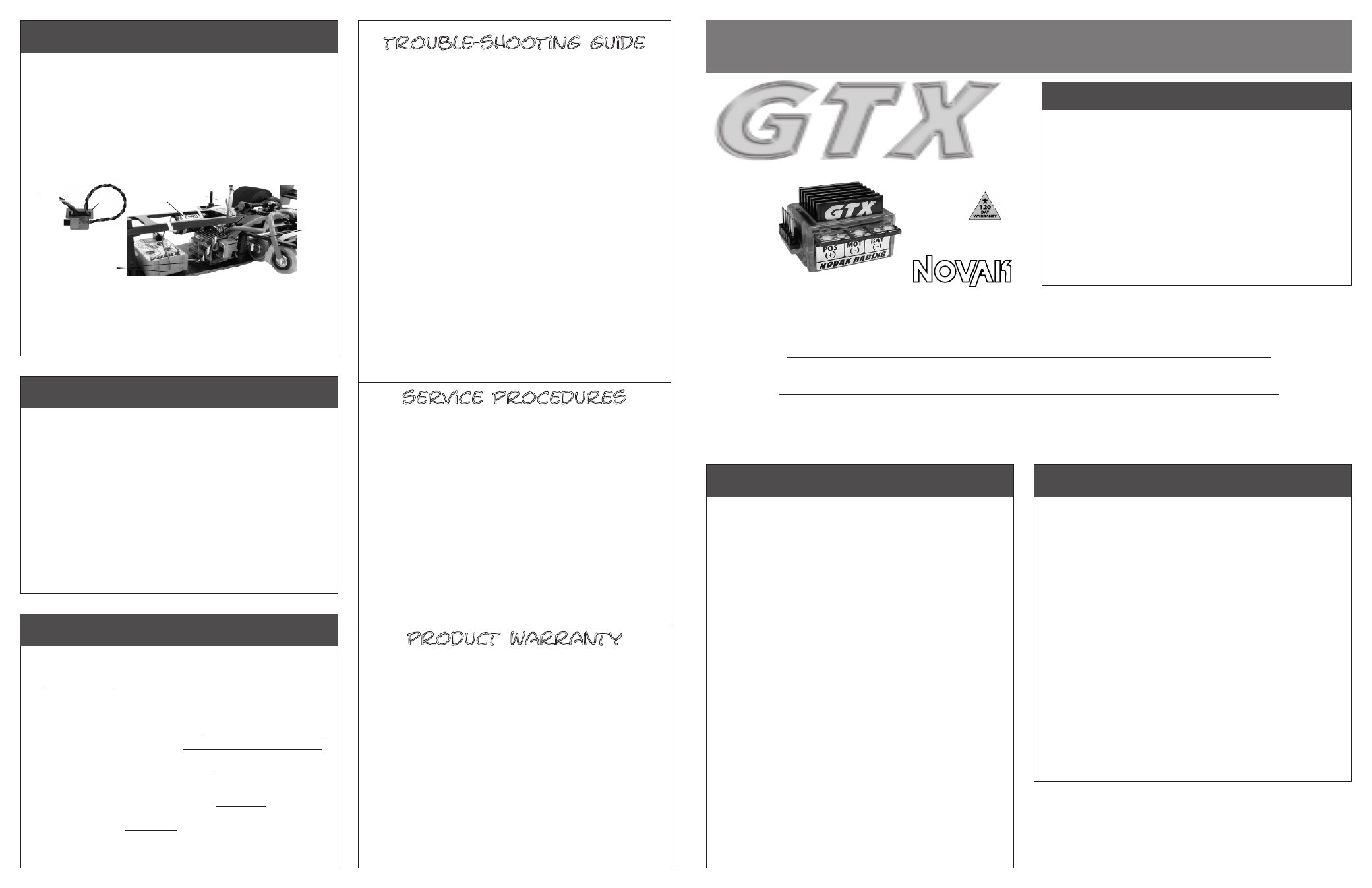
Be sure to mount the GTX where its power wires are away from other
electronics, and will not interfere with any moving parts.
• Mount GTX to the vehicle’s chassis with the included double-sided
tape
(use two layers of other double-sided tapes for adequate damping)
.
• Mount Power Capacitor to chassis with double-sided tape or tie-wrap.
If Power Cap. becomes dented/damaged, ESC failure can occur--replace
immediately.
Longer Power Capacitor wires decrease performance.
• You can use one of the included C-shaped plastic clips to secure
the ON/OFF switch to the side of the GTX’s black 5-pin power
switch/input harness plastic facing either forward or back
(see below)
.
Position switch against connector & slide clip over flange on switch.
• Be sure receiver & antenna are mounted as far from ESC, power
wires, battery, and servo as possible--these components all emit
RF noise when throttle is being applied. On graphite or aluminum
chassis vehicles, it may help to place receiver on edge with crystal
& antenna as far above chassis as possible.
Note: Mount antenna as close to receiver as possible--trail any excess wire off top
of antenna mast (cutting or coiling excess antenna wire will reduce radio range).
ON/OFF
switch
held with
C-clip
Power Capacitor
tie-wrapped to chassis
FIGURE 8
Electronics mounted
with double-sided tape
C-shaped clip holding
switch on black 5-pin
input harness plastic
clip