Step 4, Step 5, Step 6 – Novak Goat 2S Crawler Brushless ESC Programming Sheet (1970) User Manual
Page 2: Brake lights, Fusion set-up, Step 7, Trouble-shooting guide, Service procedures, Product warranty, Customer service
STEP 4
HOOK-UP INSTRUCTIONS
(Refer to set-up photo)
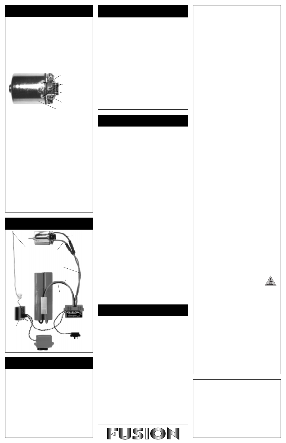
1. INSTALL MOTOR CAPACITORS
Electric motors generate radio noise that can interfere
with your receiver and cause radio problems. Included
in the accessory kit with the speed control are three
0.1
µ
F (50V) non-polarized, ceramic capacitors. These
capacitors must be installed on every motor to help
reduce the noise generated by the motor and also to
prevent possible damage to the speed control.
Solder 0.1
µ
F (50V) capacitors between:
• POSITIVE (+) motor tab & NEGATIVE (-) motor tab.
• POSITIVE (+) motor tab & GROUND tab*.
• NEGATIVE (-) motor tab & GROUND tab*.
*If your motor does not have a ground tab, solder the capacitor
leads to the can of the motor as shown below.
Negative (-) motor tab
0.1
µ
F Capacitors
Schottky diode
Positive (+) motor tab
Ground / motor can
2. CONNECT SPEED CONTROL TO THE RECEIVER
After the proper input plug plastic has been installed to
match the receiver (Refer to Step 1), plug the speed
control into the THROTTLE CHANNEL of the receiver.
3. CONNECT SPEED CONTROL TO THE BATTERY PACK
Plug the white JST connector from the speed control
into the JST/Tamiya style connector on a fully charged
6 or 7 cell battery pack (1.2 volts DC/cell). The black
wire is negative (-) and the red wire is positive (+).
4. CONNECT SPEED CONTROL TO THE MOTOR
Plug the bullet connector on the red wire (+) of the
speed control to motor positive. Plug the other bullet
connector, on the blue wire (-), to motor negative.
A wiring kit with bullet connectors and a JST/Tamiya
connector is available in Novak kit #5810.
5. OPTIONAL USE OF SCHOTTKY DIODE
The Fusion ESC does not require an external Schottky
diode. However, using one will increase the efficiency
and reduce the operating temperature of the ESC.
Solder the lead CLOSEST to the silver stripe on the body
of the Schottky diode to the POSITIVE (+) motor tab.
Solder the lead OPPOSITE the silver stripe on the body
of the Schottky to the NEGATIVE (-) motor tab.
Schottky diodes are available in Novak kit #5640.
If installed backwards, a Schottky diode will be destroyed. The body
of a bad diode will normally crack open. Replace only with Schottky
diodes that have a minimum rating of 35 volts / 8 amps.
Proper transmitter adjustment is important for optimum
performance from your speed control. The basic throttle
channel adjustments for the transmitter are as follows:
1. Set HIGH ATV or EPA to maximum setting.
[Controls amount of throw from neutral to full throttle]
2. Set LOW ATV, EPA, or ATL to maximum setting.
[Controls amount of throw from neutral to full brakes]
[Reduce this after ESC adjustment to reduce amount of brakes]
3. Set EXPONENTIAL to zero setting.
[Controls the linearity of the throttle channel]
4. Set THROTTLE CHANNEL TRIM to middle setting.
[Adjusts the neutral position of speed control]
[Increase or decrease after ESC adjustment to adjust coast
brakes––can be used to give braking in neutral trigger position]
5. Set THROTTLE CHANNEL REVERSING SWITCH to
either position.
[Do not change switch position after programming]
6. Set ELECTRONIC TRIGGER THROW ADJUSTMENT to
70% throttle and 30% brake throw (or 7:3).
[Adjusts pistol-grip transmitter’s throttle trigger throw]
7. Set MECHANICAL TRIGGER THROW ADJUSTMENT
to position with 2/3 throttle and 1/3 brake throw.
[Adjusts pistol-grip transmitter’s throttle trigger throw]
STEP 5
TRANSMITTER ADJUSTMENT
STEP 6
SPEED CONTROL ADJUSTMENT
Before beginning this step, the speed control should be
connected to the receiver and to a charged 6 or 7 cell
battery pack, and the transmitter should be adjusted.
Adjustment of your Fusion speed control is required for
proper operation. When the status LED is red, the speed
control is in the neutral position (no throttle or brake).
When the status LED is green, the speed control is either at
the full throttle or full brake position.
1. CONNECT THE BATTERY
Plug the speed control into a fully charged 6 or 7 cell
nickel-cadmium battery pack.
2. TURN ON TRANSMITTER THEN THE SPEED CONTROL
3. PRESS AND HOLD ESC’S ONE-TOUCH BUTTON
With transmitter throttle at neutral, press and hold the
ESC SET button until the status LED turns solid red.
4. RELEASE ESC SET BUTTON WHEN LED IS RED
5. PULL THROTTLE TO FULL-FORWARD POSITION
Hold it there until the status LED turns solid green.
NOTE: The motor will not run during programming even if it
is connected to the speed control.
6. PUSH THROTTLE TO FULL-BRAKE POSITION
Hold it there until the status LED blinks green.
7. RETURN TRANSMITTER THROTTLE TO NEUTRAL
Status LED will turn solid red, indicating that throttle is
at neutral and proper programming has been completed.
8. CHECK OPERATION OF THE SPEED CONTROL
Connect the motor and check for proper operation.
With no throttle or brake applied, the status LED should
be solid red and the motor should not be running. At
full throttle position, the status LED should be solid
green and the motor running full speed. At full-brake
position, the status LED should be green and the motor
should not be running.
9. SET THE COAST BRAKE AT TRANSMITTER
(optional)
Adjust the THROTTLE CHANNEL TRIM on the transmitter
to get more or less coast brake. This is accomplished by
slightly shifting the neutral position. After adjustment be
sure that the status LED is still green at full throttle.
Speed control is programmed & ready to run
!
If transmitter settings are changed at any time after the speed
control has been set-up, it will be necessary to complete the
programming sequence once again.
If you experience any problems during programming, turn off
the speed control and repeat the programming process.
BRAKE LIGHTS
The Fusion is equipped with built-in brake light circuitry to
power two LEDs.
(Novak Brake Light accessory kit #5655)
To connect brake lights to the Fusion:
1. Strip about 1/8" of insulation off of both the red and the
black small (26 gauge) wires that exit the back of the
speed control along with the battery and motor wires.
2. Strip about 1/8" of insulation off both ends of the small
(26 gauge) extension wires that are the correct length to
reach the position that the brake light is mounted.
3. Solder extension wires onto the brake light wires from
the speed control. If two LEDs are to be used, then solder
two extension wires to each brake light wire from the
speed control. Insulate solder joints with heat shrink tubing.
4. Solder end of the extension wire from the red brake light
wire to the lead on the notched/flat side of the LED. Solder
end of the extension wire from the black brake light wire
to other LED lead. Insulate solder joints with heat shrink.
Note: Some LEDs have the flat on the negative side. If LED does not
illuminate, reverse the red and black brake light wires.
TROUBLE-SHOOTING GUIDE
This section describes possible speed control problems,
causes, and solutions.
Steering Channel Works But Motor Will Not Run
• Speed control has thermally shut down––Allow ESC to
cool down––Use milder motor or smaller pinion gear.
• Check motor connections. Check motor and brushes.
• Make sure ESC is plugged into the throttle channel of
receiver. Check throttle channel operation with a servo.
Check wiring color sequence of receiver signal harness.
• Possible internal damage––Refer to Service Procedures.
Receiver Glitches/Throttle Stutters During Acceleration
• Motor capacitors broken or missing––Refer to Step 4.
• Receiver or antenna too close to speed control, power
wires, battery, or motor––Refer to Step 3.
• Bad connections––Check wiring and connectors.
• Motor brushes worn––Replace brushes.
• Excessive current to motor––Use a milder motor or a
smaller pinion gear.
Motor and Steering Servo Do Not Work
• Check wires, receiver signal harness wiring and color
sequence, radio system, crystals, battery and motor
connectors, and battery pack.
• Possible internal damage––Refer to Service Procedures.
Model Runs Slowly / Slow Acceleration
• Check motor and battery connectors––Replace if needed.
• Bad battery or motor––Check operation with another.
• Incorrect transmitter or speed control adjustment––
Refer to Steps 5 and 6.
• Optional external Schottky diode (if used) installed
backwards or damaged––Refer to Step 4.
Motor Runs Backwards
• Motor wired backwards––Check wiring and reverse.
• Backwards motor timing––Reverse motor end bell.
ESC Is Melted Or Burnt/ESC Runs With Switch Off
• Internal damage––Refer to Service Procedures.
*For more help call our Customer Service Department.
SERVICE PROCEDURES
Before sending in your Fusion for service, review the
Trouble-Shooting guide and the instructions. The ESC
may appear to have failed when other problems exist.
PLEASE NOTE: Speed controls that operate normally
when received will be charged a minimum service fee
and return shipping costs.
WHAT TO SEND: Fill out all of the information requested
on the enclosed ESC SERVICE CARD (also available on our
website) and return it with your speed control.
WARRANTY WORK: For warranty work, you MUST CLAIM
WARRANTY on the ESC SERVICE CARD and include a valid
cash register receipt with purchase date on it, or an
invoice from previous service work. If warranty provisions
have been voided there will be a service charge.
SERVICE COSTS: Customer is responsible for all service
costs (parts, labor, and shipping/handling charges). See
ESC SERVICE CARD for payment and shipping options.
ADDITIONAL NOTES:
• Hobby dealers or distributors are not authorized to
replace speed controls thought to be defective.
• If a hobby dealer returns your speed control for service,
submit a completed ESC SERVICE CARD to the dealer
and make sure it is included with the speed control.
• Novak Electronics, Inc. does not make any electronic
components (transistors, resistors, etc.) available for sale.
• To provide the most efficient service possible to our cus-
tomers, it is not our policy to contact customers by
phone or mail.
PRODUCT WARRANTY
Novak Electronics, Inc. guarantees the Fusion ESC to be free
from defects in materials and workmanship for a period of 120
days from original date of purchase (verified by dated, itemized
sales receipt). Warranty does not cover incorrect installation,
components worn by use, damage from using fewer than 6 or
more than 7 cells (1.2 volts DC/cell) input voltage, short-circuit-
ing heat sinks, cross-connection of battery/motor, damage from
incorrect installation of FET servo or receiver battery pack, dam-
age from excessive force while installing heat sinks or pushing
One-Touch button, not installing three 0.1
µ
F (50V) capacitors
on motor, splices to switch or receiver signal harnesses, using
same type and gender battery and motor connectors, damage
from disassembling case, tampering with internal electronics, al-
lowing water, moisture, or any other foreign material to enter
ESC or get onto PC board, incorrect installation of alternate in-
put plug plastic, allowing exposed wiring to short-circuit, or any
damage caused by a crash.
In no case shall our liability exceed product's original cost. We
reserve the right to modify warranty provisions without notice.
Because Novak Electronics, Inc. has no control over connection
and use of the ESC, no liability may be assumed nor will be ac-
cepted for damage resulting from the use of this product. Every
ESC is thoroughly tested and cycled before leaving our facility
and is, therefore, considered operational. By the act of connect-
ing/operating ESC, the user accepts all resulting liability.
CUSTOMER SERVICE
CUSTOMER SERVICE HOURS (PST)
Monday-Thursday: 8:00am-5:00pm
Friday: 8:00am-4:00pm
(closed every other Fri.)
(949) 833-8873 • FAX (949) 833-1631
©1998 Novak Electronics, Inc. • All Rights Reserved
No part of these operating instructions may be reproduced without the
written permission of Novak Electronics, Inc.
All Novak speed controls are designed and manufactured in the U.S.A.
Fusion™, HYPERFET III™, Polar Drive Technology™, Radio Priority
Circuitry™, One-Touch Set-Up™, Solid State RVP™, Digital Anti-Glitch
Circuitry™, & Input Plug System™ are trademarks of Novak Electronics, Inc.
Printed in the U.S.A. 11/98 • #IM-1970-1
blue wire
(motor negative)
red wire
(motor positive)
Trail excess wire
off antenna mast.
(Do not cut or coil)
Tip: Twist motor wires
to reduce radio noise!
Keep receiver
and antenna
away from
motor, servo,
battery, and
power wires.
red wire
(battery positive)
black wire
(battery
negative)
(-)
(+)
Mount switch where it
will be easy to get to.
(-)
(+)
FUSION SET-UP
Extra 0.1
µ
F capacitors
available in Novak kit #5620.
The Fusion is equipped with dual-profile throttle circuitry
that allows you to choose the right drive frequency for the
type of motor that you are using. Modified or Stock
To check or change the active throttle profile:
1. TURN ON TRANSMITTER THEN THE SPEED CONTROL
2. PRESS AND HOLD THE ESC'S ONE-TOUCH BUTTON
Continue to hold button until the status LED turns solid
green. The LED will first turn solid red, and then it will
turn solid green.
3. RELEASE THE ONE-TOUCH BUTTON
After releasing, status LED will blink red. The speed that
the LED blinks indicates the active profile.
Quick = MODIFIED
Slow = STOCK
4. While the status LED is blinking, PRESS AND RELEASE
THE ONE-TOUCH BUTTON. This will select the next
profile and the LED will blink the appropriate speed to
indicate which profile is selected.
5. Once the desired throttle profile is selected and the
One-Touch button has not been pressed for approximately
five seconds, the speed control loads the selected
profile into memory, exits the profile selection mode,
and the status LED turns solid red (neutral position). At
this point the selected throttle profile has been stored in
the speed control's non-volatile memory (it will remain
the active profile even after speed control is shut off).
The speed control is ready to run.
STEP 7
THROTTLE PROFILE SELECTION