Set-up photo step 4, Receiver battery pack, Step 7 – Novak Cyclone ESC (1767) User Manual
Page 2: Step 5, Step 6, Fet servo connection, Trouble-shooting guide, Service procedures, Product warranty, Customer service
SET-UP PHOTO
STEP 4
TRANSMITTER ADJUSTMENTS
For proper ESC operation adjust transmitter as follows:
1. Set HIGH ATV or EPA to maximum setting.
[Controls amount of throw from neutral to full throttle]
2. Set LOW ATV, EPA, or ATL to maximum setting.
[Controls amount of throw from neutral to full brakes]
[Reduce this after programming to reduce amount of brakes]
3. Set EXPONENTIAL to zero.
[Controls the linearity of the throttle channel]
4. Set THROTTLE CHANNEL TRIM to middle setting.
[Adjusts neutral position/Increases or decreases coast brakes]
5. Set CHANNEL REVERSING SWITCH to either position.
6. Set ELECTRONIC TRIGGER THROW ADJUSTMENT to 70%
throttle and 30% brake throw (or 7:3).
[Adjusts pistol-grip transmitter’s throttle trigger throw]
7. Set MECHANICAL TRIGGER THROW ADJUSTMENT to posi-
tion with 2/3 throttle and 1/3 brake throw.
[Adjusts pistol-grip transmitter’s throttle trigger throw]
Before beginning this step, the speed control should be
connected to the receiver and to a charged 4 to 7 cell
battery pack, and the transmitter should be adjusted.
1. CONNECT THE BATTERY
2. TURN ON TRANSMITTER THEN THE SPEED CONTROL
Slide the ON/OFF switch to the ON position.
3. PRESS AND HOLD ESC’S 1-TOUCH BUTTON
With the transmitter throttle in the neutral position,
press and hold the SET button on the speed control
until the status LED
turns solid red.
4. RELEASE ESC’S 1-TOUCH BUTTON
5. PULL THROTTLE TO FULL-FORWARD POSITION
Hold it there until the status LED
turns solid green.
NOTE: The motor will not run during programming even
if it is connected to the speed control.
6. PUSH THROTTLE TO FULL-BRAKE POSITION
Hold it there until the status LED
blinks green.
7. RETURN TRANSMITTER THROTTLE TO NEUTRAL
The status LED will
turn solid red, indicating that the
throttle is in the neutral position and also that proper
programming has been completed.
The speed control is programmed and ready to race!
If transmitter settings are changed, it will be necessary
to complete the programming sequence once again.
If you experience any problems during programming,
turn off the speed control and repeat programming.
RECEIVER BATTERY PACK
The Cyclone and Cyclone
TC
speed controls should not require
an external receiver battery pack for most racing situations.
The built-in Radio-Priority Circuity™ provides complete control
of the steering servos even after the main battery pack has
‘dumped’ and can no longer provide the power required to
turn the motor. However, applications with multiple high-
power servos, and some 4-cell set-ups may require an external
receiver battery pack to prevent overloading or underpowering
of the speed control’s voltage regulator.
1. Plug the external 5 cell nickel cadmium receiver battery
pack into the battery slot of the receiver.
2. Leave the speed control’s ON/OFF switch in the OFF position.
This switch is not used with this configuration.
3. Use the ON/OFF switch on the external receiver battery pack
to turn the system power on and off.
Note: If using a FET servo with an external receiver battery pack, the
separate power wire from the servo must be connected to the red or
positive servo wire. For this application do not use blue wire from ESC.
TROUBLE-SHOOTING GUIDE
This section describes possible speed control problems,
causes, and solutions.
Steering Channel Works But Motor Will Not Run
• Speed control has thermally shut down––Allow ESC to
cool down––Use milder motor or smaller pinion gear.
• Check motor connections. Check motor and brushes.
• Make sure ESC is plugged into the throttle channel of
receiver. Check throttle channel operation with a servo.
Check wiring color sequence of receiver signal harness.
• Possible internal damage––Refer to Service Procedures.
Receiver Glitches/Throttle Stutters During Acceleration
• Motor capacitors broken or missing––Refer to Step 3.
• Receiver or antenna too close to speed control, power
wires, battery, or motor––Refer to Step 2.
• Bad connections––Check wiring and connectors.
• Motor brushes worn––Replace brushes.
• Excessive current to motor––Use a milder motor or a
smaller pinion gear.
Motor and Steering Servo Do Not Work
• Check wires, receiver signal harness wiring and color
sequence, radio system, crystals, battery and motor
connectors, and battery pack.
• Possible internal damage––Refer to Service Procedures.
Model Runs Slowly / Slow Acceleration
• Check motor and battery connectors––Replace if needed.
• Bad battery or motor––Check operation with another.
• Incorrect transmitter or speed control adjustment––Refer
to Steps 4 and 5.
• Optional external Schottky diode installed backwards
or damaged––Refer to Step 3.
Motor Runs Backwards
• Motor wired backwards––Check wiring and reverse.
• Backwards motor timing––Reverse motor end bell.
ESC Is Melted Or Burnt/ESC Runs With Switch Off
• Internal damage––Refer to Service Procedures.
*For more help call our Customer Service Department.
SERVICE PROCEDURES
Before sending your Cyclone/Cyclone
TC
for service, review the
Trouble-Shooting guide and the instructions. The ESC may
appear to have failed when other problems exist.
After reviewing the instructions, if you feel that your ESC
requires service, please obtain the most current product
service options and pricing by one of the following methods:
WEBSITE: We have an abundance of information available
for all levels of speed controls, and all of our products. Print
a copy of the PRODUCT SERVICE FORM from the SERVICE
section of the website. Fill out the needed information
on this form and return it with the Novak product that
requires servicing.
PHONE/FAX/E-MAIL: If you do not have access to the inter-
net, contact our customer service department by phone,
fax, or e-mail as listed in the CUSTOMER SERVICE section
below, and they will supply you with current service options
and send you a PRODUCT SERVICE FORM.
WARRANTY SERVICE: For warranty work, you MUST CLAIM
WARRANTY on the PRODUCT SERVICE FORM and include a
valid cash register receipt with purchase date on it, or an
invoice from previous service work. If warranty provisions
have been voided there will be service charges.
ADDITIONAL NOTES:
• Hobby dealers or distributors are not authorized to
replace Novak products thought to be defective.
• If a hobby dealer returns your speed control for service,
submit a completed PRODUCT SERVICE FORM to the dealer
and make sure it is included with the speed control.
• Novak Electronics, Inc. does not make any electronic
components (transistors, resistors, etc.) available for sale.
PRODUCT WARRANTY
The Cyclone/Cyclone
TC
is guaranteed to be free from defects in
materials or workmanship for a period of 120 days from original
date of purchase (verified by dated, itemized sales receipt). Warranty
does not cover incorrect installation, components worn by use,
damage from using fewer than 4 or more than 7 cells (1.2 volts DC/
cell) input voltage, short-circuiting heat sinks, cross-connection of
battery/motor, reverse voltage application, damage resulting from
thermal overload, damage from incorrect installation of FET servo or
receiver battery pack, damage from excessive force while installing
heat sinks, not installing three 0.1µF(50V) capacitors on motor and
a power capacitor on the ESC, splices to input or switch harnesses,
damage from excessive force when using SET button or BRAKE pot
or from disassembling case, tampering with internal electronics,
allowing water, moisture, or any other foreign material to enter ESC
or get onto PC board, incorrect installation/wiring of input plug
plastic, allowing exposed wires or solder posts to short-circuit, or
any damage caused by a crash, flooding, or act of God.
In no case shall our liability exceed product’s original cost. We reserve
the right to modify warranty provisions without notice.
Because Novak Electronics, Inc. has no control over the connection
and use of the speed control, no liability may be assumed nor will
be accepted for damage resulting from the use of this product. Every
ESC is thoroughly tested and cycled before leaving our facility and
is, therefore, considered operational. By the act of connecting/operating
ESC, the user accepts all resulting liability.
CUSTOMER SERVICE
CUSTOMER SERVICE HOURS (PST)
Monday-Thursday: 8:00am-5:00pm
Friday: 8:00am-4:00pm
(closed every other Fri.)
(949) 833-8873 • FAX (949) 833-1631
e-mail: [email protected]
©2000 Novak Electronics, Inc. • All Rights Reserved
No part of these operating instructions may be reproduced without the
written permission of Novak Electronics, Inc.
All Novak speed controls are designed and manufactured in the U.S.A.
Cyclone™, Cyclone
TC
™, HYPERFET III™, Polar Drive™, One-Touch Set-
Up™, Radio Priority Circuitry™, and Digital Anti-Glitch Circuitry™ are all
trademarks of Novak Electronics, Inc.
Printed in the U.S.A. 7/2003 • #IM-1767-5
STEP 7
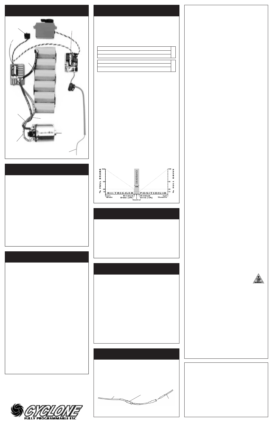
MINIMUM BRAKE ADJUSTMENT
The
BRAKE pot on the Cyclone and Cyclone
TC
allows you to
adjust the percentage of total braking power applied with the
initial trigger movement in the brake direction. Refer to above
illustration for indication of Minimum Brake Value.
• Turning
BRAKE pot clockwise, increases amount of minimum
braking up to a maximum of 75% of the total brake force.
• Turning
BRAKE pot all the way counter-clockwise, sets
the amount of minimum braking at the lowest value of
0.39%, or 1/256th (one step) of the total brake force.
STEP 5
SPEED CONTROL PROGRAMMING
STEP 6
THROTTLE PROFILE SELECTION
FET SERVO CONNECTION
The Cyclone and Cyclone
TC
speed controls are wired for con-
necting a FET servo that requires seperate power connection.
The fourth wire from the servo is connected to the small blue
24 gauge silicone wire exiting the ESC along with the signal
and switch harnesses. This wire supplies 6 volts DC to the servo,
and is controlled by the ESCs ON/OFF switch.
Be sure to install the 10µH inductor (supplied with servo) in
series with the blue FET wire as shown below.
NOTE: Do not allow the blue FET servo wire to contact the battery
or any condutive surfaces, as this may cause damage to the speed
control and will void the warranty.
NOVAK ELECTRONICS, INC.
17032 Armstrong Avenue
Irvine, CA 92614
www.teamnovak.com
Mount switch where it
will be easy to get to.
Keep receiver and antenna
away from motor, servo,
battery, and power wires.
Red wire
(battery &
motor positive)
Tip: Twist motor
wires to reduce
radio noise!
Trail excess wire
off antenna mast.
(Do not cut or coil)
Blue wire
(motor negative)
Black wire
(battery negative)
(–)
(–)
(+)
(+)
The Cyclone and Cyclone
TC
allow you to choose between three
user-selectable throttle profiles that are programmed at the
factory. This chart gives the specifics of each profile:
%
kHz
%
kHz
1
Stock
6.0
5.86
6.0
3.90 OFF
2
Drag Brake
6.0
7.80
6.0
5.86 ON
3
**
Modified
7.0
15.60
1.5
3.90 OFF
1 **World Cup 7.0
15.60
1.5
3.90 OFF
2 High Traction 3.0
11.70
2.0
5.86 OFF
3 Touring Stock 3.0
7.80
3.0
7.80 OFF
Experiment with each profile to determine which works best for you!
1. TURN ON THE TRANSMITTER
2. TURN ON THE SPEED CONTROL
3. PRESS & HOLD ESC’S 1-TOUCH BUTTON until the status LED
turns solid green. The LED will first turn red, then a few
seconds later it will turn green.
4. RELEASE 1-TOUCH BUTTON and then the status LED will
begin to blink red. The number of times the LED blinks
indicates the profile number selected.
5. PRESS & RELEASE 1-TOUCH BUTTON TO SELECT PROFILE Each
press will change to the next consecutive profile number.
NOTE: After profile #3, the sequence begins again at profile #1.
6. If 1-TOUCH button is not pushed for about five seconds,
the ESC LOADS THE SELECTED PROFILE INTO MEMORY, and the
status LED
turns solid red, indicating that the speed control
has exited the profile selection mode and is in neutral.
Both speed controls can store a custom fourth profile that is created
with the optional programming device, the
Pit Wizard (#1035). Once
a custom profile has been created and downloaded into the ESC,
there will be four profiles to choose from. The Pit Wizard comes with
complete details on creating your own custom profiles and gives you
the ability to modify the following parameters: Neutral Postion, Full
Throttle Position, Full Brake Position, Dead Band Value, Drag Brake
Value, Drag Brake Frequency*, Drive PWM Frequency*, Minimum Drive
Value, Brake PWM Frequency*, and the Drag Brake Toggle.
*Adjustable from 122-23,400 Hz
Illustration below shows graphical display of adjustable parameters
Profile
Description
Dead Band Drive Frequency
Minimum Drive
Brake Frequency
Dr
.Brake T
oggle
CYCLONE
CYCLONE
TC
(**default)
Fourth wire
from servo.
10µH inductor
Blue FET servo wire
from speed control
Blue wire
(FET servo)