Good quality radio system suggested, Eiger set-up photo, Proper gear selection – Novak Club (55-1852-1) User Manual
Page 2: Voltage cut-off circuitry temperature monitoring, Step 3–connect receiver, Fm am 2.4 ghz
black wire
(Rx negative)
red wire
(Rx positive)
white wire
(Rx signal)
positive
fan pin
negative
fan pin
one-touch
button
With higher performance electronic systems, undesirable radio system noise
may occur when used with lower quality radio systems.
High quality 2.4GHz radio systems are the best to use--
Be careful with cheap
2.4GHz systems.
FM radio systems are acceptable, as long as the system is high quality.
AM radio systems are NOT recommended.
Good Quality Radio System Suggested
FM
AM
2.4 GHz
Do not use
OK to use
Best to use
eiger set-up photo
w
w
w
.t
ea
m
n
ov
a
k
.c
om
step 2–connect motor
step 1–mount esc
Mount the speed control so that the power wires are as far away from other
electronics as possible, and will not interfere with the vehicle’s moving parts.
Select an installation location that has good airflow for cooling the ESC as
this will result in efficient operation.
1. MOUNT SPEED CONTROL IN VEHICLE
Use the included double-sided tape to mount the ESC to the vehicle’s
chassis (do NOT use glue). Avoid contact with chassis side walls or other
vehicle components to avoid vibration damage.
Be sure receiver & antenna are mounted as far from ESC, power wires,
battery, and servo as possible--These components all emit RF noise.
Note: Mount antenna as close to receiver as possible--trail excess wire off top of
antenna mast (cutting/coiling excess wire reduces radio range--2.4GHz too).
2. INSTALL ON/OFF SWITCH
Use included double-sided tape to mount switch where it will be easy to
access--select a place where it will not get damaged/switched OFF in a crash.
3. SECURE POWERCAP & POWER WIRES TO AVOID VIBRATION DAMAGE
To prevent vibration damage, use the included tie-wraps to secure
PowerCap (the capacitor on smaller silicone wires soldered to the ESC’s positive
& negative battery tabs) to the ESC’s heavier gauge battery power wires.
You should also tie-wrap the power wires together or to a point on the
vehicle to avoid vibration & stress on the ESC’s solder tabs.
1. SELECT PROPER MOTOR FOR OPTIMUM PERFORMANCE
The ESC’s different Drive/Brake Modes each work best with different motors.
Select the proper motor for the given application & DO NOT over-gear.
2. INSTALL PINION GEAR & ADJUST MOTOR FOR PROPER GEAR MESH
Tighten the pinion’s set screw onto the flat of motor shaft. Align the pinion
and the spur gears.
A. You NEED a small amount of play between the pinion & spur gears
(about thickness of a piece of paper)
--check free play at several points around
spur gear to ensure a proper mesh
(Make sure gear mesh is NOT TOO TIGHT)
.
B. Tighten the motor mounting screws--Avoid using excessive force that
could break the screws or strip the threaded holes in motor.
3. CONNECT MOTOR POWER WIRES TO MOTOR
A.
Connect the ESC’s
BLUE Phase ‘A’ silicone motor power wire to the bullet
connector on motor’s
BLUE power wire.
B.
Connect the ESC’s
YELLOW Phase ‘B’ silicone motor power wire to the
bullet connector on motor’s
YELLOW power wire.
B.
Connect the ESC’s
ORANGE Phase ‘C’ silicone motor power wire to the
bullet connector on motor’s
ORANGE power wire.
4. CONNECT MOTOR SENSOR HARNESS TO ESC
Insert the 6-pin connector of the motor’s sensor harness in the ESC’s sensor
harness socket--connector is keyed and only inserts in one direection.
5. CHECK FOR PROPER GEARING DURING INITIAL RUNS
ESC and Motor SHOULD NOT GET EXCESSIVELY HOT--Lower the gearing
or check the vehicle’s drive train for binding or other problems if you
experience high operating temperatures.
With ESC connected to a charged battery and the receiver:
1. TURN ON THE TRANSMITTER’S POWER
2. PRESS & HOLD ESC’S ONE-TOUCH/SET BUTTON
3. TURN ON THE SPEED CONTROL’S POWER
With transmitter at neutral (still pressing SET button), slide ESC’s switch
to ON position.
4. CONTINUE HOLDING SET BUTTON UNTIL RED LED COMES ON
5. RELEASE SET BUTTON AS SOON AS RED LED TURNS ON
6. PULL TRANSMITTER THROTTLE TO FULL-ON POSITION
Hold it there until green status LED
turns solid green. (Motor won’t run during programming).
7. PUSH TRANSMITTER THROTTLE TO FULL-BRAKE/REVERSE
Hold it there until the green status LED
blinks green.
8. RETURN TRANSMITTER THROTTLE TO NEUTRAL
The red status LED will
turn solid red, indicating that speed control is at neutral
and that proper programming has been completed.
If transmitter settings are changed, the One-Touch Programming must be repeated.
If you experience any problems, turn off ESC and repeat One-Touch.
NOTE: One-Touch Programming reverts ESC back to factory-default settings.
STEP 5-one-touch programming
transmitter adjustments
Note: Transmitter adjustments may not be required to properly complete
the speed control’s One-Touch programming. If, however, you have any
problems with the programming, adjust your transmitter settings as listed
below and repeat
ONE-TOUCH PROGRAMMING.
THROTTLE CHANNEL ADJUSTMENTS
A. Set HIGH ATV
or
EPA
to 100%. [amount of throw at full throttle]
B. Set LOW ATV, EPA, or ATL
to 100%. [amount of throw at full brakes]
C. Set EXPONENTIAL
to
zero setting.
[throttle channel linearity]
D. Set THROTTLE CHANNEL REVERSING SWITCH
to either position.
E. Set THROTTLE CHANNEL TRIM
to
middle
.
[adjusts neutral position]
F. Set ELECTRONIC TRIGGER THROW
to 70% throttle/30% brake (or 7:3)--best
for racing. Set to 50%/50% for full time use with reverse for best performance.
G. Set MECHANICAL TRIGGER THROW
to 2/3 throttle and 1/3 brake throw position.
•NOT ALL TRANSMITTERS HAVE ALL OF THESE ADJUSTMENTS•
step 3–connect receiver
The ESC has a user-replaceable input harness
with a 2mm mini plug on ESC end of it and the
industry-standard connector on receiver end.
The ESC works with all major radio brand’s
new receivers. Some very old receivers need
the wiring sequence changed in the plastic
3-pin connector on the receiver end--
Receiver/
servo may be damaged if sequence is incorrect.
For instructions on changing the wiring
sequences on older receivers, visit our web site.
1. CONNECT 2mm MINI PLUG TO RECEIVER HARNESS PINS ON ESC
Insert the 2mm mini plug of receiver input harness onto the 3-pin Rx
header on the ESC.
White wire goes on the left side pin as shown above.
2. CONNECT RECEIVER HARNESS TO RECEIVER
Insert 3-pin connector of receiver harness into Ch.2 (throttle) slot of receiver.
Using a Non-Novak External BEC
To use a non-Novak brand BEC with this speed control, please follow the BEC
manufacturer’s instructions. Remove the RED wire from the plug plastic on
the ESC’s receiver input signal harness, and leave the ESC’s ON/OFF switch
in the ‘ON’ position at all times.
Using a Novak External BEC
To use a Novak BEC with this speed control, remove the RED wire from the
plug plastic on the ESC’s receiver input signal harness, and leave the ESC’s
ON/OFF switch in the ‘ON’ position at all times.
Connect the Novak BEC’s main power input leads (heavier gauge silicone wire) to
ESC’s Positive & Negative battery solder tabs (RED to Positive & BLACK to Negative).
Plug the BEC’s receiver power output lead into the slot of any open/unused
channel of your receiver.
Use the BEC’s ON/OFF switch to turn the system’s power ON & OFF--or you
can leave both swtiches on and connect/disconnect battery to turn power on & off.
external bec connection
OPTIONAL RECEIVER PACK USAGE
step 4–connect battery
1. CONNECT ESC’S BATTERY CONNECTOR TO BATTERY PACK
Connect the speed control’s battery connector to a fully charged 1S or
2S LiPo battery pack.
To change the battery connector on the ESC to a different type, we suggest
using low-loss high power connectors like Dean’s Ultra Plug.
• Use polarized connectors. Reverse voltage will damage ESC & void warranty.
• Use a female connector on battery packs to avoid shorting.
ESC is designed for LiPo battery operation only. Voltage Cut-Off circuitry
will not allow proper operation with NiMH or NiCd type batteries.
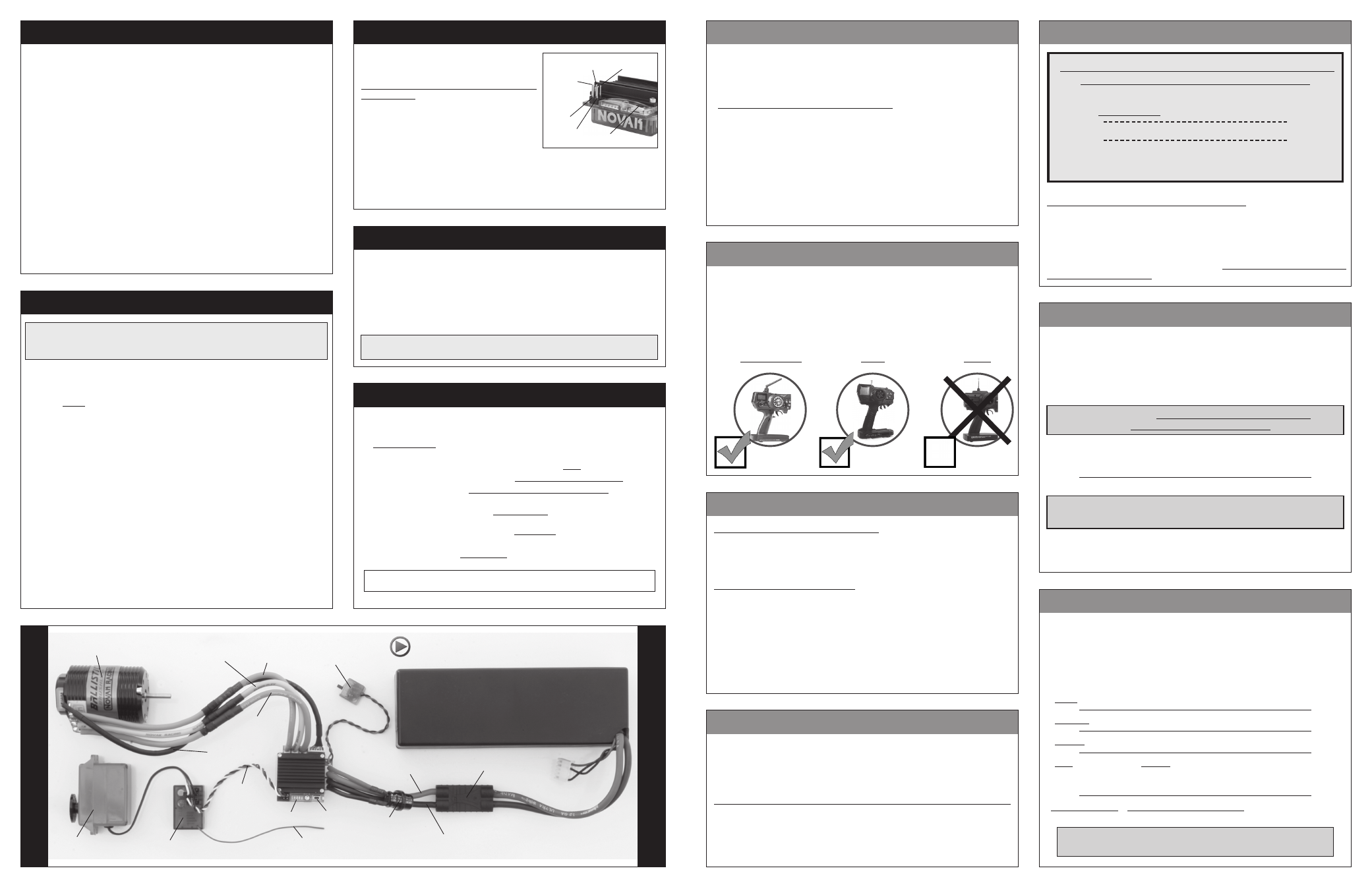
ESC
ON/OFF
Switch
User-
replaceable
input signal
harness
(Ch.2)
Servo plugged into
steering ch. (#1)
Set
button
Status LEDs
FM Receiver
Trail excess wire off top
of antenna mast
Novak sensor-based
brushless motor
Blue motor
phase wire
(Phase A)
Yellow motor
phase wire
(Phase B)
Orange
motor phase wire
(Phase C)
Sensor harness
Red power wire
(battery positive)
Black power wire
(battery negative)
Polarized, high-power
battery connector
PowerCap
(tie-wrapped to power wires)
2S LiPo
Battery pack
(
or 4-7 cell NiMH or NiCd pack
)
*Note: Battery pack, servo, and
receiver are not included.
For informative installation and how-to videos,
visit the Team Novak Channel on YouTube®.
proper gear selection
This speed control features Novak’s Smart-Stop Auto-Detect Voltage Cut-Off
Circuitry built-in. When used properly, this feature will allow you to safely
use 2S LiPo batteries, without letting the cells drop below their critical safety
voltage during operation that results in premature battery failure.
The Smart-Stop’s Auto-Detect looks at the voltage of the battery pack that
is connected to the speed control, and turns itself on or off accordingly.
The Smart Stop circuitry
is ACTIVE when connected to 2S LiPo packs,
and the circuitry
is OFF when connected to 1S LiPo battery packs.
Re-charge battery after Smart-Stop circuitry shuts off throttle
Even though the battery pack’s voltage will rise (after a short resting period) to
a level high enough to run motor again, this is not good for the LiPo batteries.
Reaching critical safety voltage too many times can damage the cells.
DO NOT RUN VEHICLE AFTER SMART-STOP
HAS SHUT DOWN THROTTLE OUTPUT
•This ESC is designed to operate on LiPo type batteries ONLY•
If attempting to use this speed control with NiCd or NiMH type cells,
the ESC’s throttle output will be shut off very early into the run.
voltage cut-off circuitry
temperature monitoring
This speed control has a built-in diagnostic temperature monitoring feature
that lets you quickly and easily check the ESC’s operating temperature at any
time with a click of the ESC’s push-button.
While connected to a battery and powered ON,
simply tap the ESC’s SET
button and one of the on-board LED lights will flash 4 times to indicate the
operating temperature of the speed control:
BLUE flashing LED = normal operating temp--
136-147°F (58-64°C).
YELLOW flashing LED = medium operating temp--
148-167°F (65-75°C).
GREEN flashing LED = hot operating temp--
168-194°F (76-90°C).
RED flashing LED =
hottest operating temp--195-215°F (91-102°C).
You are now pushing the ESC extremely hard and should be very
careful to avoid overheating and possible thermal shut-down.
All LEDs flashing = DANGEROUS operating temp--
216-239°F (103-115°C).
Your ESC is now about to thermally shut-down.
Reduce the pinion size/check drive train to avoid ESC
overheating that could result in potential damage.
Motor operating temperature is the ONLY
way to properly set vehicle gearing
The Motor and Speed Control should not exceed
160°F MAX at any time during run
!
Change the gearing to avoid overheating!
DO NOT FREE-REV MOTOR
!
Free-running your brushless motor in a no-load condition can cause rotor failure
& ESC transistor damage that will not be covered by the product’s warranty.
Because of potential overheating danger and ESC & motor damage/failure,
you must start with VERY small pinion sizes and check ESC & motor
operating temperatures at multiple times during your initial runs after ESC
installation. This is the only way to prevent excessive heating.
If ESC & motor temperatures remain low & stable, you can slowly increase
the pinion size while again monitoring the temperatures to determine the
safe gearing for your vehicle, motor, and climate/track conditions. Because
these variables can change or be modified,
you MUST continually monitor
ESC & motor temperatures to protect your electronics from damage.
Novak recommends the use of an external receiver battery pack to supply
power to the electronics when using very high-power servos, as these servos
put excessive load on the speed control’s internal BEC.
Using an external reciever pack will greatly increase life span of
your ESC, as this is a leading cause of speed control failure.
To use an External Receiver Battery Pack to Power the Electronics:
1. Plug the 5 cell (1.2 VDC/Cell) receiver battery pack into the battery slot (or
any open/unused channel) of the receiver.
2. Remove the red wire from ESC’s input receiver harness (insulate the red wire).
3. To turn the vehicle ON, switch the receiver pack’s power switch
ON. Then,
turn the ESC’s power switch
ON.
4. To turn vehicle OFF, turn ESC’s switch
OFF, then turn receiver pack’s switch OFF.