Esc set-up photo, Step 4–wire esc to battery, Step 3–wire esc to motor – Novak Activ8 Basic Set-Up (1725) User Manual
Page 2: Figure 2), Good quality radio system suggested, Step 1–connect input harness, Step 2–mount esc, Brushless motor precautions, 4 ghz
This ESC has a user-replaceable input harness with the industry-standard JST
connector on both the ESC and receiver ends of it (also making it reversible).
This ESC works with all
major radio brand’s new
receivers (see Figure 1 at
right for connection of the
included user-replaceable
input harness), however,
some very old receivers
must have the wiring
sequence in the plastic
3-pin JST connector
housing changed on
the receiver end.
NOTE: The receiver & servo electronics may be damaged
if the wiring sequence is incorrect.
For instructions on changing the wiring sequence for older receivers, visit the
Novak Web site (www.teamnovak.com).
P3
step 1–connect input harness
step 3–Wire ESC to Motor
step 2–mount esc
Mount the speed control so that the power wires are as far away from other
electronics as possible. Make sure that the speed control or the power wires
will not interfere with any moving parts in the vehicle. Select a location that
has good cooling and allows airflow through heat sinks.
If the speed control gets air flow, it will run cooler; and
that means, it will be more efficient & faster!
1. MOUNT SPEED CONTROL IN VEHICLE
Use the included double-sided tape to mount the speed control in vehicle
(do not use glue). Avoid contact with side walls or other chassis components
to avoid vibration damage--double layer the tape for even more dampening.
Be sure receiver & antenna are mounted as far from ESC, power wires, battery,
& servo as possible--these components all emit RF noise when throttle is
applied. On graphite or aluminum chassis vehicles, it may help to place
receiver on edge with crystal & antenna as far above chassis as possible.
Note: Mount antenna as close to receiver as possible--trail any
excess wire off top of antenna mast (cutting or coiling excess
antenna wire will reduce radio range).
2. INSTALL ON/OFF SWITCH
Use the included double-sided tape or a small screw to mount the switch
where it will be easy to access--be sure to select a position where it will
not get damaged or get switched OFF during a crash or roll-over.
3. SECURE POWER WIRES
To avoid vibration damage, tie wrap the power wires together or to a
point on the vehicle.
If using an external Power Trans-Cap module, secure it to chassis:
Use the included double-sided tape, or a tie-wrap, to mount Power Trans-
Cap Module to the vehicle’s chassis or shock tower. Module can also be
tie-wrapped along the power wires--this requires less space on the chassis and
can also provide good isolation from vibration.
This ESC is compatible with all Novak 550/540-sized & 15-Series (1/8th
Scale size) brushless sensor-based motors. It is not compatible with brushed
type motors or sensorless brushless motors.
1. INSTALL PINION GEAR
Tighten pinion’s set screw on flat of motor shaft. Align pinion & spur gears.
2. ADJUST MOTOR FOR PROPER GEAR MESH
A. Adjust the motor position for proper free play. You NEED a small amount
of play between the pinion gear and the spur gear (about the thickness
of a piece of paper)–check the free play at several positions around the
spur gear to ensure a proper mesh
(just in case the gears are out of round).
MAKE SURE THE PINION/SPUR GEAR MESH IS NOT TOO TIGHT!
If gear mesh is too tight, motor shaft breakage can occur.
B. Tighten motor mounting screws–Avoid using excessive force that could
break screws or strip the threaded holes in motor.
3. CHECK FOR PROPER GEARING
The brushless motor & ESC should NOT be hotter than 160°F after a run.
Lower the gearing until both ESC & motor are under this temperature. The
cooler the ESC runs, the better the performance of the system.
**Check out our NovaGear App, available on the Apple
TM
iTunes Store, for help selecting
the proper starting points for gearing in your brushless motor applications**
4. SOLDER MOTOR POWER PHASE WIRES TO MOTOR
A.
Cut the ESC’s
BLUE silicone motor power wires to the desired length,
and strip 1/8-1/4” of insulation from the end of each wire. Tightly twist
the exposed strands of wire and tin with solder.
B.
Place the
Phase ‘A’ motor wire onto motor’s ‘A’ solder tab & solder. Use
soldering iron to apply heat to exposed wire; begin adding solder to tip
of iron & to wire. Add just enough solder to form a clean & continuous
joint from the plated area of solder tab up onto the wire.
C.
Solder the ESC’s
Phase ‘B’ motor wire to the motor’s ‘B’ solder tab.
D.
Solder the ESC’s
Phase ‘C’ motor wire to the motor’s ‘C’ solder tab.
IMPORTANT NOTE: DO NOT OVERHEAT SOLDER TABS
Prolonged/excessive heating of solder tabs (motor or ESC) will damage PCB.
Note: Make sure no wire strands have strayed to an adjacent solder tab, this will
result in short-circuiting & severe ESC damage, which will void the warranty.
5. CONNECT MOTOR SENSOR HARNESS TO ESC
Insert the 6-pin connector of the motor’s sensor harness into ESC’s sensor
harness socket—connector is keyed and only inserts in one direction. Novak
offers Shielded Brushless Sensor Harnesses in three lengths: 4”/100mm
(Novak #5351), 6”/150mm (Novak #5352) & 9”/230mm (Novak #5353).
FACTORY-INSTALLED POWER CAPACITORS REQUIRED
The factory-installed Power Capacitors MUST be used.
If Power Capacitors become
dented, bulged, or damaged, ESC failure can occur--replace immediately.
DO NOT USE SCHOTTKY DIODES
Schottky diodes must NOT be used with reversible ESCs.
Schottky diode usage will damage the ESC & void warranty.
MOTOR CAPACITORS NOT NEEDED
Novak brushless motors do not require external motor capacitors.
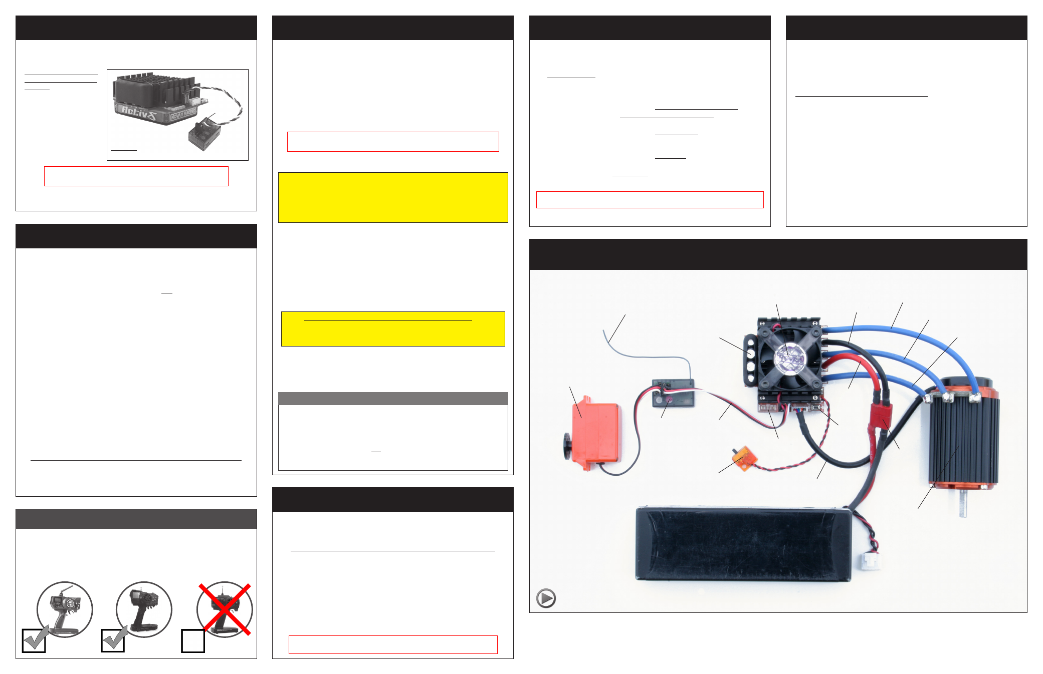
ESC SET-UP PHOTO
(FIGURE 2)
ESC
ON/OFF
Switch
User-
replaceable
input signal
harness
(Ch.2)
Servo plugged into
steering ch. (#1)
P2
Set
button
Status
LEDs
Good Quality Radio System Suggested
bRUSHLESS mOtOr precautions
Cooling fan with ‘X’ guard
(refer to Fig. 3)
FM Receiver
Trail excess wire off top
of antenna mast
Novak sensor-based
brushless motor
Phase ‘C’
motor wire
Sensor harness
Red power wire
(battery positive)
Black power wire
(battery negative)
Battery
connector
Power
Capacitors
step 4–Wire ESC to Battery
With the higher performance of brushless systems, undesirable radio system
noise may occur when used with lower quality radio systems. 2.4GHz radio
systems are the best to use. FM radio systems are acceptable, as long as
the system is high quality. AM radio systems are not recommended.
Battery pack
(2-4S LiPo or 6-14 cell NiMH/NiCd)
*Battery pack, servo, receiver, and battery connector are not included.
For informative installation and how-to videos,
visit the Team Novak Channel on YouTube®.
Best to use
2.4 GHz
OK to use
FM
Do not use
AM
With the ESC connected to (at least) a charged battery pack, the receiver, and
the brushless motor’s sensor harness:
1. TURN ON THE TRANSMITTER’S POWER
2. PRESS & HOLD ESC’S ONE-TOUCH/SET BUTTON
3. TURN ON THE SPEED CONTROL’S POWER
With transmitter throttle at neutral, and still pressing the SET button, slide the ESC’s
ON/OFF switch to ON position.
4. CONTINUE HOLDING SET BUTTON UNTIL RED LED COMES ON
5. RELEASE SET BUTTON AS SOON AS LED TURNS RED
6. PULL TRANSMITTER THROTTLE TO FULL-ON POSITION
Hold it there until the green status LED
turns solid green.
Note: Motor will not run during programming even if connected.
7. PUSH TRANSMITTER THROTTLE TO FULL-BRAKE/REVERSE
Hold it there until the green status LED
blinks green.
8. RETURN TRANSMITTER THROTTLE TO NEUTRAL
The red status LED will
turn solid red, indicating that speed control is at neutral
and that proper programming has been completed. Blue & yellow LEDs will also be
on indicating Minimum Brake (blue) & Drag Brake (yellow) settings are at levels above 0%.
If transmitter settings are changed, the One-Touch Programming must be repeated.
If you experience any problems, turn off ESC and repeat One-Touch.
NOTE: Whenever the One-Touch Programming set-up is performed, the
speed control will automatically revert back to the factory-default settings.
STEP 5-one-touch programming
transmitter adjustments
Transmitter adjustments may not be required to properly complete the
One-Touch programming of the speed control. However, should you have
any problems completing the
ONE-TOUCH PROGRAMMING, adjust the
settings on your transmitter as listed below, then repeat the
ONE-TOUCH
PROGRAMMING as described in Step 5.
THROTTLE CHANNEL ADJUSTMENTS
A. Set HIGH ATV
or
EPA
to 100%. [amount of throw at full throttle]
B. Set LOW ATV, EPA, or ATL
to 100%. [amount of throw at full brakes]
C. Set EXPONENTIAL
to
zero setting.
[throttle channel linearity]
D. Set THROTTLE CHANNEL REV. SWITCH
to either position.
E. Set THROTTLE CHANNEL TRIM
to
middle
setting.
[adjusts neutral position/increases or decreases coast brakes]
F. Set ELECTRONIC TRIGGER THROW ADJUSTMENT
to 70% throttle and
30% brake throw (or 7:3)–best for racing ESCs. Set to 50% throttle and 50% brake
for full time use with reverse to get the best performance in reverse.
[adjusts trigger throw electronic/digital pistol-grip transmitters]
G. Set MECHANICAL TRIGGER THROW ADJUSTMENT
to position with 2/3
throttle and 1/3 brake throw.
[adjusts trigger throw mechanical/analog pistol-grip transmitters]
•NOT ALL TRANSMITTERS HAVE ALL OF THESE ADJUSTMENTS•
w w w . t e a m n o v a k . c o m
FIGURE 1
Input harness plugged into channel 2 of the receiver.
To connect the ESC to the main battery pack using connectors, we suggest low-
loss high power connectors like Dean’s Ultra Plug or Novak Power Connectors.
• Use polarized connectors. Reverse voltage will damage ESC & void warranty.
• Use a female connector on battery packs to avoid shorting.
1. INSTALL BATTERY CONNECTOR
A.
Cut the RED & BLACK silicone battery power wire to the desired length, and strip
1/8”–3/16” of insulation from the end of each wire. Tightly twist and tin the ends
of the exposed wire with solder.
B. Solder the ESC’s RED (+) battery wire to the connector’s POSITIVE (+) contact.
C. Solder the ESC’s
BLACK (–) battery wire to the connector’s NEGATIVE (–) contact.
D. Cover the exposed solder joints with heat shrink tubing to prevent possible short circuits.
2. CONNECT ESC TO BATTERY PACK
Connect the speed control’s battery connector to a fully charged 2-4S LiPo
or 6-14 NiMH cells (1.2 VDC/cell) battery pack.
NOTE: If using NiMH batteries, the Voltage Cut-Off Circuitry must be turned
OFF for proper ESC operation (refer to Track Guide).
Phase ‘B’
motor wire
Phase ‘A’
motor wire