Installation instructions, Overheating -- warning, Motor timing adjustment – Novak Brushless Motor: Vulcan Motor (55-3640-1 Rev.3) User Manual
Page 2
MOTOR TIMING ADJUSTMENT
MOTOR TIMING ADJUSTMENT
1. NO MOTOR CAPACITORS & SCHOTTKY NEEDED
Novak brushless motors do not need motor capacitors or external
Schottky diodes--Schottky diode usage will damage ESC.
2. CHECK MOTOR SCREW LENGTH & INSTALL MOTOR
• Insert the motor mounting screws that came with your vehicle
through the motor mounting plate.
540-size motors need no
more than 1/8” of screw extending past the vehicle’s mounting
plate (2-4mm)--Too little can strip the motor’s threads, too much
will cause internal motor damage & will void warranty.
• Attach motor to vehicle’s motor mount using one of the sets of
threaded mounting holes--
select a mounting position that keeps the
solder tabs clear of conductive surfaces like aluminum or graphite.
3. INSTALL PINION GEAR (see GEAR SELECTION)
Install pinion on motor and test fit in vehicle to align pinion and
spur gears. Tighten pinion’s set screw on the flat of motor shaft.
4. ADJUST MOTOR FOR PROPER GEAR MESH
• Adjust the motor position for proper amount of free play. You
NEED to have a small amount of play between the pinion gear
and the spur gear (about the thickness of piece of paper)--check
the free play at several positions around the spur gear to
ensure a proper mesh
(just in case the gears are out of round).
MAKE SURE THE PINION/SPUR GEAR MESH IS NOT TOO TIGHT!
If gear mesh is too tight, motor shaft breakage can occur.
• Tighten motor mounting screws--Avoid using excessive force,
as the threaded holes in motor could become stripped.
5. SOLDER MOTOR POWER WIRES
(skip this step if motor is wired to ESC)
• Determine the best routing in vehicle for the motor’s silicone
power wires--avoid any moving parts & suspension.
• Prepare ends of power wires by stripping 1/8-1/4” of
insulation from end of wire. Tin wire ends with solder.
• Lay tinned end of the wire flat on the solder tab and solder
wires to proper tabs of the motor (refer to phase markings
below solder tabs). Apply heat with soldering iron to the power
wire and solder tab--begin adding solder to tip of iron and to
wire--
Add just enough solder to form a clean & continuous joint
from the solder tab up onto the wire.
WARNING: Be sure no wire strands have strayed to an adjacent solder tab--this
will cause short-circuiting, damage electronics, & void product’s warranty.
IMPORTANT NOTE: DO NOT OVERHEAT SOLDER TABS
Prolonged or excessive heating of the solder tabs will
cause damage & void the product’s warranty.
6. CONNECT MOTOR SENSOR HARNESS
• Determine the best routing in vehicle for the motor’s sensor
harness--securing sensor harness to the motor power wires with a
tie-wrap can provide a good location & also act as a strain relief.
• Connect one end of the harness to the ESC & the other end
to the motor’s sensor harness connector located under the
back bearing cap. Be sure the plug on the end of the harness
inserts all the way into the sensor harness connector--the plug
& connector are keyed and will only go together one direction.
INSTALLATION INSTRUCTIONS
INSTALLATION INSTRUCTIONS
GEAR SELECTION (Important)
GEAR SELECTION (Important)
vented front can
vented front can
hand-wound
stator
hand-wound
stator
low-loss solder tabs
low-loss solder tabs
timing
assembly
timing
assembly
sensor harness
connector
sensor harness
connector
back
end bell
back
end bell
bearing
cap
bearing
cap
M2.5 x 10mm
flat head
cap screws
M2.5 x 10mm
flat head
cap screws
fish paper
insulator
fish paper
insulator
fiberglass
stamping
insulator
fiberglass
stamping
insulator
4-40 x 1.75”
socket head
cap screws
4-40 x 1.75”
socket head
cap screws
VULCAN MOTOR
Exploded View
VULCAN MOTOR
Exploded View
The Vulcan’s timing is adjusted by loosening the bearing cap’s three M2.5 flat head
screws, rotating cap to desired setting, & re-tightening screws--DON’T OVER-TIGHTEN.
The motor’s factory timing is marked with a
timing label located on the side of the back
bearing cap and lines up with a groove milled
into the top of the back end bell.
Retarding the timing will reduce RPM range &
increase torque--this usually reduces current
draw and lowers operating temperatures.
For each timing mark (on label) reduced,
increase pinion gear size by one tooth to
accommodate lower RPM range.
Advancing the timing will increase motor’s
RPM range, reduce its torque, and make it
less efficient, plus it will pull more current,
resulting in higher operating temperatures.
Adjusting timing beyond the 45°
mark on timing label will result in dangerously
high current draw & excessive heating that can lead to ESC & motor failure.
MELTED STATORS ARE NOT COVERED BY THE WARRANTY!
timing groove
timing groove
Refer to ‘Accessories’ section for
available replacement components.
Refer to ‘Accessories’ section for
available replacement components.
w w w . t e a m n o v a k . c o m
w w w . t e a m n o v a k . c o m
Motor operating temperature is the ONLY
way to properly set the maximum vehicle gearing
The motor should be 160-175°F MAX at end of run!
Temperatures above 175°F will weaken the magnet & may
melt the coils! This voids warranty & can damage ESC!
Change the gearing to avoid overheating.
Because of the potential danger of overheating, ESC/motor damage & failure, you must
start with VERY small pinion sizes and check ESC & motor temperatures at multiple times
throughout a run. This is the only way to ensure that you are not causing excessive heating.
If ESC & motor temperatures remain low & stable, you can slowly increase the pinion size
while again monitoring the temperatures to determine the safe gearing for your vehicle,
motor, and climate/track conditions. Because these variables can change or be modified,
you
MUST continually monitor ESC & motor temperatures to protect your electronics from damage.
If you do not change gearing after switching to brushless, you will be over
geared and will have slow acceleration & excessive temperatures!
Because of the broad power band of brushless, you can go 1-2 teeth higher pinion for
shorter high speed runs, but continued usage will produce excessive ESC & motor heating.
Brushless Motors in Rock Crawling Applications
Brushless crawler motors and ESCs should not get very hot with typical gear reduction rock
crawling transmissions--if you notice excessive temperatures, check motor & drive train for free
operation or adjust gearing to lower temperature. Refer to vehicle’s manual for proper gearing.
See our website for additional gearing information
OVERHEATING -- WARNING
!
OVERHEATING -- WARNING
!
Due to the nature of racing, timing advance speed controls, motor tolerances/settings,
vehicle performance, and track conditions, it has become virtually impossible to provide
installation and operation recommendations that will allow you to use these motors at
their highest performance levels without the potential for unwanted damage.
You must, use extreme caution when setting up these electronics and carefully test your
application to avoid overloading and overheating either the speed control or the motor.
These are racing electronics used in racing conditions, and therefore damage as the result
of excessive overheating WILL NOT be covered under the product’s factory warranty.
silicone
grommet
silicone
grommet
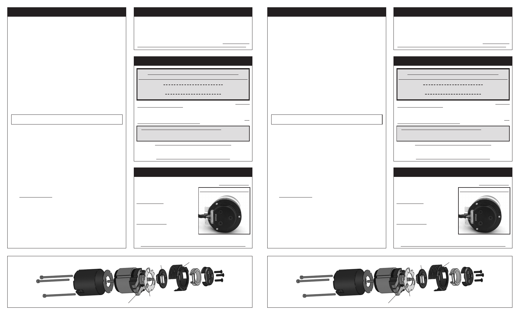
ZERO DEGREE CRAWLER TIMING
Align sensor harness with solder tabs.
ZERO DEGREE CRAWLER TIMING
Align sensor harness with solder tabs.