Custom programming options, Throttle profile selection, M2 dig software flow chart – Novak Brushed Speed Control: M2 Dig Field Guide- 4 Profile Model (55-1846P-1 Rev. 1.2) User Manual
Page 2: M2 dig throttle profiles, Status led order
P6
throttle profile selection
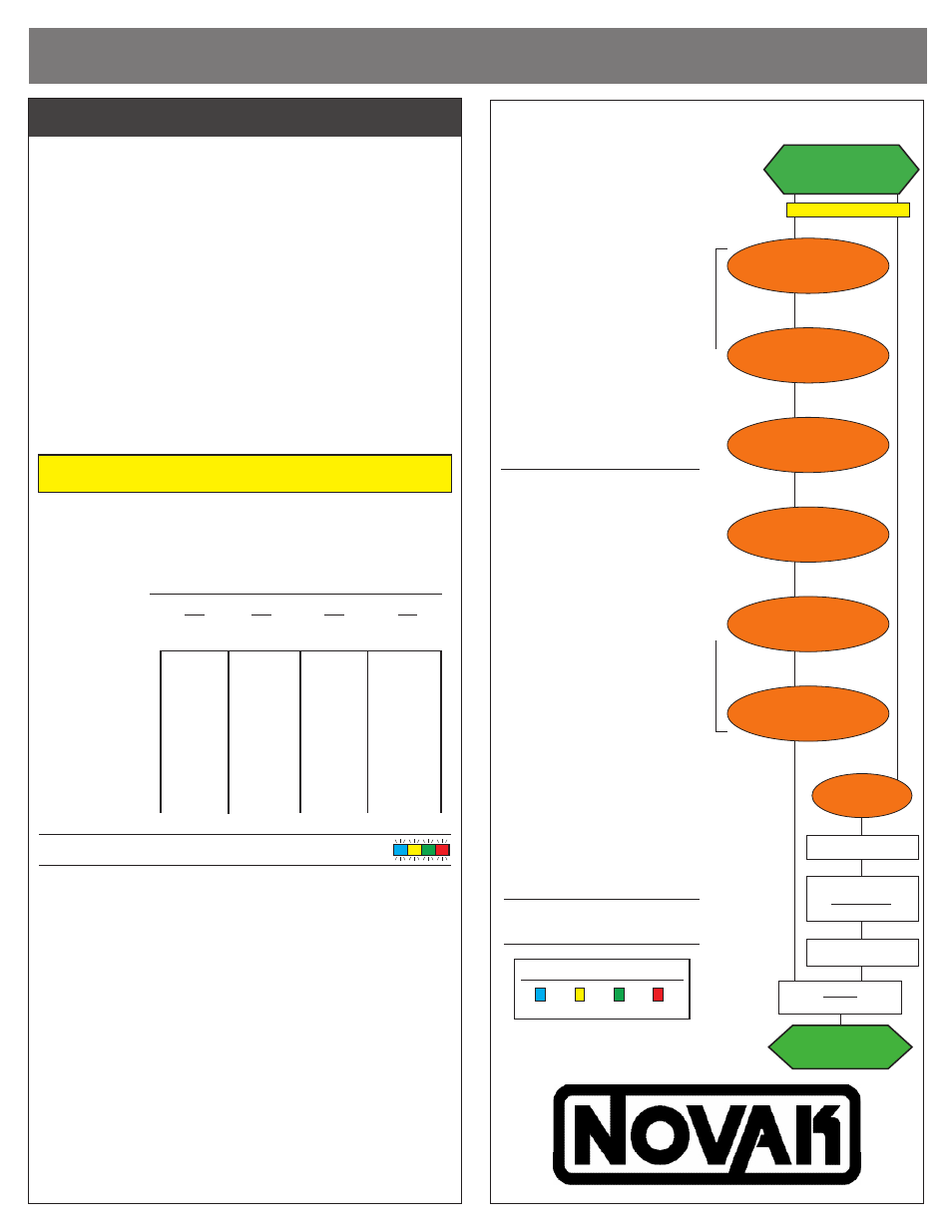
m2 dig software flow chart
@NEUTRAL
BLUE-YELLOW-RED
LEDs on solid
DRAG BRAKE
BLUE & YELLOW
PROFILE
all LEDs (flashing)
DEAD BAND
BLUE & GREEN
MIN. DRIVE
YELLOW
press & hold SET button
continue holding ESC’
s SET button to skip steps here
LEDs roll off
ESC exits programming
# flashes = active profile
if pressed within 3 sec.
of all LEDs flashing
active profile changed
if not pressed within
3sec. of all LEDs flashing
VOLTAGE CUT-OFF
YELLOW-RED
DIG POWER
BLUE-GREEN-RED
DRIVE FREQ.
GREEN-RED
NEUTRAL
BLUE-YELLOW-RED
LEDs on solid
STATUS LED ORDER:
BLUE YELLOW GREEN
RED
CUSTOM programmiNG options
The M2 Dig 3S Dual Brush speed control is equipped with
4 user-selectable
Throttle Profiles, as shown below:
• PROFILE 1 – Dig Mode – When the AUX/3rd switch/dial is thrown, the
dig function for either the front or rear motor (depending on the switch
position) will be engaged. The transmitter must have either a proportional
AUX switch or a simple three-position AUX switch.
• PROFILE 2 – Proportional Dig Mode – In this mode, the amount of dig
power applied to each motor is directly proportional to the position of the
AUX/3rd channel. The transmitter must have an AUX/3rd channel and
must have a proportional-style switch or control similar to a dial or knob.
• PROFILE 3 – Single Output Mode – This mode is used for standard
two-channel operation with either single or dual-motor control. There
is no dig function in this profile. See
STEP 1 for proper input harness
connections and
STEP 3 for proper motor connections.
• PROFILE 4 – Dual Independent Mode – This mode is used for indepen-
dent control of two motors. The throttle trigger controls one motor, and
the AUX/3rd channel controls the second motor. All the settings such
as drag brake, dead band, and minimum drive equally apply to both
channels. There is no dig function in this profile.
WARNING: When switching from Profile #3 to Profile #4, the motor wires
MUST BE DISCONNECTED FIRST or damage will occur to the ESC
NOTE: The M2 Dig has the ability to run on either 2S or3S LiPo or LiFe
batteries via Novak’s auto detect software. When the voltage cut-off cir-
cuitry is active (see programming on reverse side to turn ON/OFF), the ESC
automatically switches to the proper cut-off voltage.
M2 DIG THROTTLE PROFILES
#1
#2
#3
#4
Dig
Proportional Single
Dual
Dig (Default) Mode
Independent
Reverse
100%
100%
100%
100%
Programmable
yes
yes
yes
yes
Drag/Hill Brake
97%
97%
97%
97%
Dig Power
70%
70%
N/A
N/A
Dead Band
5%
5%
5%
5%
Minimum Drive
3%
3%
3%
3%
Drive Frequency
2.5kHz
2.5kHz
2.5kHz
2.5kHz
Voltage Cut-Off
LiPo
LiPo
LiPo
LiPo
selecting throttle profiles:
all LEDs
With ESC on & connected to a charged battery and transmitter ON:
1. PRESS & HOLD THE ESC’S ONE-TOUCH SET BUTTON
Continue to hold SET button on ESC until all LEDs turn on.
Note: You will continue holding past all the LED programming
indicators in the speed control’s software as shown in the flow
chart on this sheet.
2. RELEASE SET BUTTON AS SOON AS ALL LEDs COME ON
Once released, the four status LEDs will flash to indicate what Throttle
Profile is currently selected. The number of times the LEDs flash indicates
the Brushless Throttle Profile selection (1 of 4). Default is 2 flashes to
indicate Throttle Profile #2.
3. QUICK PRESS (& release) SET BUTTON TO CHANGE SELECTION
Each press will change to the next consecutive Throttle Profile.
4. STORE SELECTION & EXIT TO NEUTRAL
Once the desired profile is selected, press and hold the SET button for 1-2
seconds. When the LEDs begin to scroll off, release the SET button and the
blue, yellow, & red LEDs will turn on solid. At this point, the ESC is at neutral
and ready to go.
The M2 Dig 3S ESC features several
parameters that can be customized
to fine-tune the speed control’s feel
& response to your liking.
The flow chart below and the
adjustment steps to the right
describe the different parameters
and how they effect the ESC.
One-Touch Programming must be
completed before customization
o f p a r a m e t e r s , a s a l l E S C
parameters except Throttle Profile
are defaulted back to the factory
settings whenever the One-Touch
Programming is performed.
DEFAULT SETTINGS FOR THE
ESC PARAMETERS ARE LISTED
IN BOLD IN THE TABLES TO
THE RIGHT
TO CHANGE PARAMETER SETTINGS:
1. CONNECT THE ESC TO A
RECEIVER AND A CHARGED
BATTERY PACK & TURN ON
TRANSMITTER
2. SLIDE THE ESC’s ON/OFF
SWITCH TO ‘ON’ POSITION
3. WITH ESC AT NEUTRAL, PRESS
& HOLD SET BUTTON
Release ESC’s SET button once LEDs
are lit for the desired setting.
To skip a parameter, continue
to press & hold SET button until
desired parameter is reached.
4. SELECT PARAMETER VALUE
LED flashes to indicate active setting
(refer to tables at right). Quick press
& release SET button to select
desired setting.
5. PRESS & HOLD SET BUTTON TO
STORE NEW SELECTION
When SET button is pressed and
held for about 1-2 seconds,
the
new selection is stored in ESC’s
memory—Status LEDs will scroll across
to indicate ESC is exiting programming
& ESC returns to neutral.
There is no time constraint during
selection of custom parameters.