Esc programming, Drive, Brake mode – Novak Brushed Speed Control: Eiger & Eiger Pro -- V1 (low profile heat sinks) (55-1835-1.2) User Manual
Page 2: Dead band, Drive frequency, Voltage cut-off, Good quality radio system suggested, Set-up photo, Step 3–connect receiver, Step 4–connect battery
ESC programming
This ESC features 4 adjustable parameters to fine-tune the ESC’s feel &
operation for your needs. NOTE: You must first complete the ESC’s One-
Touch Programming before adjusting the ESC parameters.
DEFAULT PARAMETER SETTINGS FOR ARE LISTED IN BOLD IN TABLES BELOW
TO CHANGE PARAMETER SETTINGS:
1. CONNECT THE ESC TO A CHARGED BATTERY PACK & RECEIVER.
2. TURN ON TRANSMITTER.
2. SLIDE THE ESC’s ON/OFF SWITCH TO ‘ON’ POSITION
3. WITH ESC AT NEUTRAL, PRESS & HOLD ESC’s SET BUTTON
Release ESC’s SET button once the LED is lit for the setting you wish to change.
To skip, continue to press & hold SET button until desired parameter is reached.
4. SELECT PARAMETER VALUE
LED flashes to indicate active setting (refer to tables). Quick press & release SET
button to select desired setting.
5. PRESS & HOLD SET BUTTON TO STORE NEW SELECTION
When button is pressed & held for 1 second,
new selection is stored in ESC’s
memory. Status LEDs will scroll across to confirm ESC programming & ESC returns to neutral.
There is no time constraint during selection of custom parameters.
drive
/
brake mode
#1 DRIVE/BRAKE MODE SETTINGS
(1 of 5)
BLUE LED
Drive mode and braking type & amount being applied.
>> Setting 1 = Basher Mode--Push Brakes/Forward/Reverse--Regular driving
(No braking applied at neutral/double-pump trigger for reverse). Setting 2 = Servo
Mode--Forward/Reverse--Robotic applications
(No braking/No reverse delay).
Settings 3-5 = Hill Brake settings--Rock crawling
(Low, Medium, or High Brakes).
Setting
(# flashes)
1
2
3
4
5
Drive/Br. Mode:
Bash
Servo
Crawl-Lo Crawl-Md Crawl-Hi
dead band
#2 DEAD BAND SETTINGS
(1 of 5)
RED LED
The space between Minimum Brake and Minimum Drive, with Neutral in the middle.
>> Increasing this setting increases amount of ‘free play’, or distance the
transmitter’s trigger must move before forward drive or braking begins.
This is useful for triggers that don’t center accurately or have worn pots.
Setting
(# of flashes)
1
2
3
4
5
Dead Band (%):
3
5
6
8
12
DRIVE FREQUENCY
#3 DRIVE FREQUENCY SELECTION
(1 of 5)
GREEN LED
How the ESC’s throttle response feels with respect to the transmitter’s trigger input.
>> Increasing the Drive Frequency makes the throttle response feel
smoother and more controllable.
Setting
(# of flashes)
1
2
3
4
5
Drive Freq. (
KHz
):
1.0
1.5
2.0
6.2
8.0
voltage cut-off
#4 VOLTAGE CUT-OFF SELECTION
(1 of 2)
YELLOW LED
>> Changing this setting enables or disables the built-in Smart Stop
cut-off circuitry and sets the voltage cut-off point based on how many
cells are being used for the vehicle’s main battery pack.
DO NOT USE LiPo’s WITH VOLTAGE CUT-OFF CIRCUITRY TURNED OFF
Setting
(# of flashes)
1
2
LiPo Voltage Cut-Off:
OFF
(NiMH/NiCd)
ON
(LiPo)
NOTE: Yellow LED will stay on at all times when the Voltage Cut-Off is active.
restoring factory defaults
Every time the ESC’s One-Touch Programming is performed,
ESC automatically revert sback to the factory default settings.
Note: ESC Parameter values are subject to change due to ongoing development. Refer to our web site for updated values and more information on ESC parameters.
With higher performance electronic systems, undesirable radio system noise
may occur when used with lower quality radio systems.
High quality 2.4GHz radio systems are the best to use--
Be careful with cheap
2.4GHz systems.
FM radio systems are acceptable, as long as the system is high quality.
AM radio systems are NOT recommended.
Good Quality Radio System Suggested
FM
AM
2.4 GHz
Do not use
OK to use
Best to use
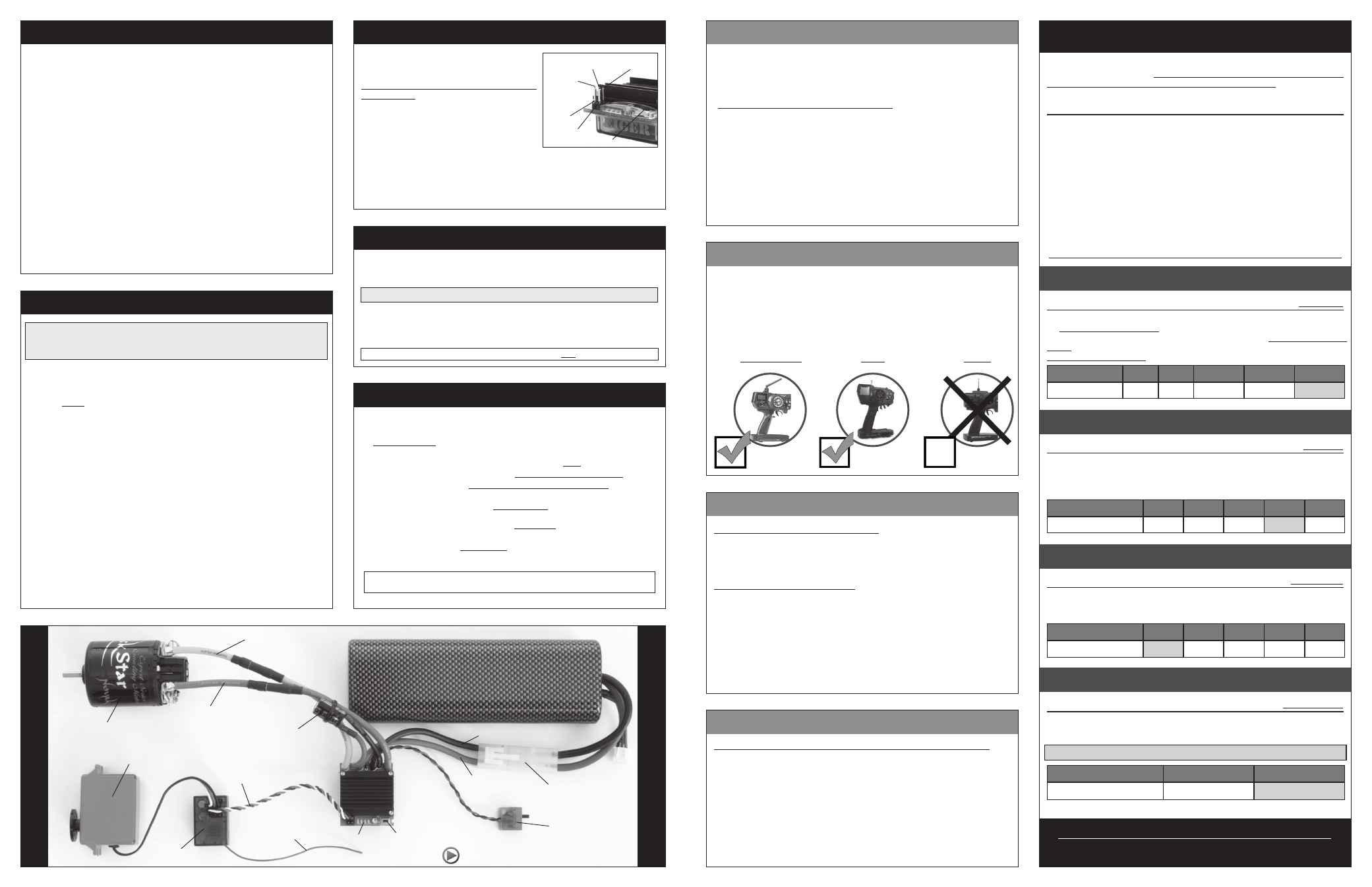
set-up photo
w
w
w
.t
ea
m
n
ov
a
k
.c
om
step 2–connect motor
step 1–mount esc
Mount the speed control so that the power wires are as far away from other
electronics as possible, and will not interfere with the vehicle’s moving parts.
Select an installation location that has good airflow for cooling the ESC as
this will result in efficient operation.
1. MOUNT SPEED CONTROL IN VEHICLE
Use the included double-sided tape to mount the ESC to the vehicle’s
chassis (do NOT use glue). Avoid contact with chassis side walls or other
vehicle components to avoid vibration damage.
Be sure receiver & antenna are mounted as far from ESC, power wires,
battery, and servo as possible--These components all emit RF noise.
Note: Mount antenna as close to receiver as possible--trail excess wire off top of
antenna mast (cutting/coiling excess wire reduces radio range--2.4GHz too).
2. INSTALL ON/OFF SWITCH
Use included double-sided tape to mount switch where it will be easy to
access--select a place where it will not get damaged/switched OFF in a crash.
3. SECURE POWERCAP & POWER WIRES TO AVOID VIBRATION DAMAGE
To prevent vibration damage, use the included tie-wraps to secure
PowerCap (the capacitor on smaller silicone wires soldered to the ESC’s positive
& negative battery tabs) to the ESC’s heavier gauge battery power wires.
You should also tie-wrap the power wires together or to a point on the
vehicle to avoid vibration & stress on the ESC’s solder tabs.
1. SELECT PROPER MOTOR FOR OPTIMUM PERFORMANCE
The ESC’s different Drive/Brake Modes each work best with different motors.
Select the proper motor for the given application & DO NOT over-gear.
2. INSTALL PINION GEAR & ADJUST MOTOR FOR PROPER GEAR MESH
Tighten the pinion’s set screw onto the flat of motor shaft. Align the pinion
and the spur gears.
A. You NEED to have a small amount of play between the pinion & spur
gear (about thickness of a piece of paper)--be sure to check for free play
at several points around spur gear to ensure a proper mesh
(Make
sure gear mesh is NOT TOO TIGHT).
B. Tighten the motor mounting screws--Avoid using excessive force that
could break the screws or strip the threaded holes in motor.
3. CONNECT MOTOR POWER WIRES TO MOTOR
The ESC’s motor leads come with gold-plated bullet-style motor
connectors factory-installed for quick and easy motor connection. These
connectors are also available separately from Novak in different sizes for
other motors or wiring needs.
A.
Connect the ESC’s
YELLOW ‘Positive’ silicone motor power wire to the
bullet connector on the motor’s
POSITIVE power wire.
B.
Connect
BLUE ‘Negative’ power wire to connector on motor’s NEGATIVE
wire—You may need to swap connectors (plus/minus) for reverse rotation.
4. CHECK FOR PROPER GEARING DURING INITIAL RUNS
Crawler motors/ESCs generally DO NOT get very hot--Lower the gearing
or check the vehicle’s drive train for binding or other problems if you
experience high operating temperatures.
With ESC connected to a charged battery and the receiver:
1. TURN ON THE TRANSMITTER’S POWER
2. PRESS & HOLD ESC’S ONE-TOUCH/SET BUTTON
3. TURN ON THE SPEED CONTROL’S POWER
With transmitter at neutral (still pressing SET button), slide ESC’s switch
to ON position.
4. CONTINUE HOLDING SET BUTTON UNTIL RED LED COMES ON
5. RELEASE SET BUTTON AS SOON AS RED LED TURNS ON
6. PULL TRANSMITTER THROTTLE TO FULL-ON POSITION
Hold it there until green status LED
turns solid green. (Motor won’t run during programming).
7. PUSH TRANSMITTER THROTTLE TO FULL-BRAKE/REVERSE
Hold it there until the green status LED
blinks green.
8. RETURN TRANSMITTER THROTTLE TO NEUTRAL
The red status LED will
turn solid red, indicating that speed control is at neutral
and that proper programming has been completed.
[Yellow LED on at neutral indicates that LiPo Voltage Cut-Off feature is turned ON]
If transmitter settings are changed, the One-Touch Programming must be repeated.
If you experience any problems, turn off ESC and repeat One-Touch.
NOTE: One-Touch Programming reverts ESC back to factory-default settings.
STEP 5-one-touch programming
transmitter adjustments
Note: Transmitter adjustments may not be required to properly complete
the speed control’s One-Touch programming. If, however, you have any
problems with the programming, adjust your transmitter settings as listed
below and repeat
ONE-TOUCH PROGRAMMING.
THROTTLE CHANNEL ADJUSTMENTS
A. Set HIGH ATV
or
EPA
to 100%. [amount of throw at full throttle]
B. Set LOW ATV, EPA, or ATL
to 100%. [amount of throw at full brakes]
C. Set EXPONENTIAL
to
zero setting.
[throttle channel linearity]
D. Set THROTTLE CHANNEL REVERSING SWITCH
to either position.
E. Set THROTTLE CHANNEL TRIM
to
middle
.
[adjusts neutral position]
F. Set ELECTRONIC TRIGGER THROW
to 70% throttle/30% brake (or 7:3)--best
for racing. Set to 50%/50% for full time use with reverse for best performance.
G. Set MECHANICAL TRIGGER THROW
to 2/3 throttle and 1/3 brake throw position.
•NOT ALL TRANSMITTERS HAVE ALL OF THESE ADJUSTMENTS•
step 3–connect receiver
The ESC has a user-replaceable input harness
with a 2mm mini plug on ESC end of it and the
industry-standard connector on receiver end.
The ESC works with all major radio brand’s
new receivers. Some very old receivers need
the wiring sequence changed in the plastic
3-pin connector on the receiver end--
Receiver/
servo may be damaged if sequence is incorrect.
For instructions on changing the wiring
sequences on older receivers, visit our web site.
1. CONNECT 2mm MINI PLUG TO RECEIVER HARNESS PINS ON ESC
Insert the 2mm mini plug of receiver input harness onto the 3-pin Rx
header on the ESC.
White wire goes on the left side pin as shown above.
2. CONNECT RECEIVER HARNESS TO RECEIVER
Insert 3-pin connector of receiver harness into Ch.2 (throttle) slot of receiver.
black wire
(Rx negative)
red wire
(Rx positive)
white wire
(Rx signal)
positive
fan pin
negative
fan pin one-touch button
ESC
ON/OFF
Switch
User-replaceable
input signal
harness
(Ch.2)
Servo plugged into
steering ch. (#1)
Set button
Status LEDs
FM Receiver
Trail excess wire off
top of antenna mast
Brush-type motor
Blue (negative)
motor wire
Yellow (positive)
motor wire
Red power wire
(battery positive)
Black power wire
(battery negative)
Battery connector
PowerCap
(tie-wrapped to power wires)
Battery pack
• 2-3S* LiPo or 4-9 cell NiMH/NiCd •
(*External BEC required for 3S operation)
For informative installation and how-to videos,
visit the Team Novak Channel on YouTube®.
*Note: Battery pack, servo, and receiver are not included.
external bec connection
OPTIONAL RECEIVER PACK USAGE
To use an external receiver battery pack to power the electronics:
1. Plug the 5 cell (1.2VDC/cell) receiver pack into the battery slot of receiver.
2. Switch the receiver pack ON. Next, turn the ESC’s switch ON, then OFF
to allow the ESC to be powered by the external power source.
3. Turn the receiver pack’s switch OFF to turn the vehicle OFF.
ALTERNATIVE METHOD
1. Plug the 5 cell (1.2 VDC/Cell) receiver pack into the battery slot of receiver.
2. Unplug the ESC’s red wire from input receiver harness (insulate the red wire).
3. To turn the vehicle ON, switch the receiver pack ON, then turn ESC’s switch ON.
4. To turn the vehicle’s electronics OFF, turn ESC’s switch OFF, then turn
receiver pack’s switch OFF.
step 4–connect battery
1. CONNECT ESC’S BATTERY CONNECTOR TO BATTERY PACK
Connect the speed control’s battery connector to a fully charged 2-3S
LiPo or 4-9 cell NiMH (1.2 VDC/cell) battery pack.
External 3S-rated BEC is required for 3S
(or 8-9cell NiMH)
operation of ESC
To change the battery connector on the ESC to a different type, we suggest
using low-loss high power connectors like Dean’s Ultra Plug.
• Use polarized connectors. Reverse voltage will damage ESC & void warranty.
• Use a female connector on battery packs to avoid shorting.
If using NiMH cells, Voltage Cut-Off Circuitry must be turned OFF after One-Touch Programming.
Using a Non-Novak External BEC
To use a non-Novak brand BEC with this ESC, follow the BEC manufacturer’s
installation instructions. Remove the RED wire from the plug plastic on the
ESC’s receiver input signal harness. Turn ON the ESC’s power switch, then
turn ON the BEC’s power switch.
Using a Novak External BEC
Connect the Novak BEC’s main power input leads (the heavier gauge silicone
wires) to the ESC’s Positive & Negative battery solder tabs (RED to Positive,
BLACK to Negative).
Plug the JST connector on the BEC’s receiver power output lead into any
open channel of your receiver.
Remove the RED wire from the plug plastic on the ESC’s receiver input signal
harness--Insulate removed wire to avoid short circuits, as it is “live”.
Turn ON the ESC’s power switch, then turn ON the BEC’s power switch.
Turn the system’s power OFF in the reverse order--BEC then ESC.