Brushless profile programming, Throttle profile, Drag – Novak Brushed Speed Control: Eiger & Eiger Pro Field Guide-- NEW version ESCs (standard height heat sinks) (55-1835P-1.4) User Manual
Page 3: Hill brake, Brake frequency, Drive frequency, Dead band, Minimum drive, Motor rotation, Voltage cut-off
brushless profile
programming
throttle profile
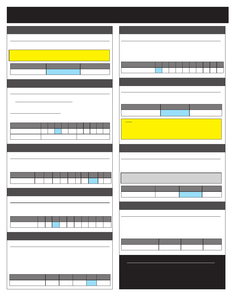
#1 THROTTLE PROFILE SELECTION
(1 of 2) BLUE-RED-WHITE LEDs
>> Changing this setting switches the ESC’s motor control output.
To use with a Sensor-Based Brushless Motor, change to Setting #2 .
Note: When performing One-Touch Set-Up (page 1), be sure to leave the brushless
motor wires DISCONNECTED. After the One-Touch Set-Up is done, change the
Throttle Profile Setting to #2, then connect the brushless motor power wires.
Setting
(# of flashes)
1
2
Throttle Profile:
Brush
Brushless
drag
/
hill brake
#2 DRAG/HILL BRAKE SETTINGS
(1 of 10) BLUE LED
Amount of braking being applied while transmitter is at neutral. AKA ‘hold’ brakes.
>> Settings 1-5 are Standard Drag Brake settings--less aggressive
braking for rock racing (setting #1 applies no braking while trigger is
at neutral).
Settings 6-10 are Power Hill Brake settings (ESC applies power to mo-
tor to ‘hold’ its position)--very strong rock crawling Hill/Hold braking.
Note: you must have a Novak Crawler brushless motor to have power brakes.
Setting
(# of flashes)
1
2
3
4
5
6
7
8
9 10
Drag Brake (%):
0
40 60 95 100 40 65 70 80 90
Brake Type:
Drag Brakes
Power Hill Brakes
BRAKE FREQUENCY
#3 BRAKE FREQUENCY SELECTION
(1 of 10) RED LED
How the ESC’s braking response feels with respect to the transmitter’s trigger input.
>> Increasing the Brake Frequency makes the brake response feel
smoother and more controllable.
Setting
(# of flashes)
1
2
3
4
5
6
7
8
9 10
BrakeFreq.
(KHz)
:
13.5 10.5 5.5 4.5 3.5 3 2.5 2.25 2 1.6
DRIVE FREQUENCY
#4 DRIVE FREQUENCY SELECTION
(1 of 10) BLUE & WHITE LEDs
How the ESC’s throttle response feels with respect to the transmitter’s trigger input.
>> Increasing the Drive Frequency makes the throttle response feel
smoother and more controllable.
Setting
(# of flashes)
1
2
3
4
5
6
7
8
9
10
Drive Freq.
(KHz)
:
32 30 25 23 21 16 14 12 10
8
dead band
#5 DEAD BAND SETTINGS
(1 of 5) BLUE-YELLOW-RED LEDs
Dead Band is the space between Minimum Brake and Minimum Drive, with
Neutral in the middle.
>> Increasing this setting increases amount of ‘free play’, or distance
the transmitter’s trigger must move before the ESC sends forward
drive or braking signal to the motor.
This is useful for transmitters with triggers that don’t center accurately
or have worn pots and do not return to neutral properly.
Setting
(# of flashes)
1
2
3
4
5
Dead Band (%):
2
3
4
5
8
minimum drive
#6 MINIMUM DRIVE SETTINGS
(1 of 10) BLUE-YELLOW-GREEN LEDs
Minimum Drive is the amount of forward drive applied with first pulse of transmit-
ter throttle information sent.
>> Increasing this setting starts the forward drive at a stronger level.
This is useful to compensate for heavier vehicles to minimize the
amount of trigger throw required before effective drive is applied.
Setting
(# of flashes)
1
2
3
4
5
6
7
8
9 10
Minimum Drive (%):
0
1
2
3
4
6
8 10 12 15
motor rotation
#7 MOTOR ROTATION SELECTION
(1 of 2) BLUE-GREEN-RED LEDs
>> Changing this setting changes the rotation direction of the motor’s
output/pinion shaft. Counter-clockwise rotation is standard in most
vehicles.
Setting
(# of flashes)
1
2
Rotation Direction:
CCW
Q
CW
P
Note: Your brushless motor must have the mechanical timing set to 30° for
proper operation in forward and reverse direction. All Novak brushless motors,
except for Novak Crawling motors, are factory timed to 30°. To change the
mechanical timing on your Novak motor, refer to the Novak website (www.
teamnovak.com) in the TECH INFO section. Having the motor set at 0° will
draw excessive current in the reverse direction and may cause damage.
VOLTAGE cut-off
#8 VOLTAGE CUT-OFF
(1 of 3) BLUE-YELLOW-GREEN-RED LEDs
>> Changing this setting enables or disables the ESC’s built-in Smart
Stop cut-off circuitry, and also sets the voltage cut-off point based on
what type of battery is being used for the vehicle’s main battery pack.
DO NOT USE LiPo/LiFe BATTERIES WITH THE ESC’S
VOLTAGE CUT-OFF CIRCUITRY TURNED OFF
Setting
(# of flashes)
1
2
3
Voltage Cut-Off Type:
OFF
(NiMH/NiCd)
LiPo
LiFe
hall sensor test
#9 MOTOR SENSOR TEST BLINKING BLUE LED
>> This diagnostic feature allows you to check the functionality of
your brushless motor’s hall effect sensors & sensor harness
(and its
connections at the ESC and motor). Once activated, slowly rotate the mo-
tor’s output/pinion shaft and the appropriate LED will light up if a
signal is received for that sensor in the motor. Refer to ‘MOTOR HALL
SENSOR TEST’ section.
Motor Hall Sensor
A
B
C
LED Color:
BLUE
YELLOW
RED
restoring factory defaults
Every time the ESC’s One-Touch Set-Up is
performed, the ESC will automatically revert
back to the factory default settings.
For brushless motors, be sure the power wires are disconnected
before One-Touch Set-Up is performed.
Note: ESC Parameter values are subject to change due to ongoing development.
P3
Refer to our web site for updated values and more information on ESC parameters.