Custom programming, Drag brake, Minimum brake – Novak Brushless Speed Control: Super-Tuner Brain Board Upgrade Track Guide (55-1746P-1 Rev.2) User Manual
Page 2: Brake frequency, Hall sensor test, Timing level ’s, Timing start rpm, Timing final rpm, Timing rpm range, Throttle profile
drag brake
#2 DRAG BRAKE SETTINGS
(1 of 10)
BLUE LED
Amount of braking being applied while transmitter is at neutral. AKA ‘coast’ brakes.
>> Increasing this setting makes the motor slow down more without
pushing the transmitter’s trigger into the brake/reverse direction.
Setting
(# of flashes)
1
2
3
4
5
6
7
8
9 10
Drag Brake (%):
0
3
6
9 12 15 18 21 24 30
minimum brake
#3 MINIMUM BRAKE SETTINGS
(1 of 10)
YELLOW LED
Amount of braking applied with the first pulse of transmitter braking information sent.
>> Increasing this setting starts the braking at a stronger/higher
level. This is useful to compensate for heavier vehicles to minimize the
amount of trigger throw required before effective braking is applied.
Setting
(# of flashes)
1
2
3
4
5
6
7
8
9 10
Minimum Brake (%):
0
3
6
9 12 15 18 21 24 30
BRAKE FREQUENCY
#4 BRAKE FREQUENCY SELECTION
(1 of 10)
RED LED
How the ESC’s braking response feels with respect to the transmitter’s trigger input.
>> Increasing the Brake Frequency makes the brake response feel
smoother and more controlable.
Setting
(# of flashes)
1
2
3
4
5
6
7
8
9
10
Brake Freq. (KHz):
1.6 2.0 2.2 2.5 3.0 3.5 4.5 5.0 5.7 10.0
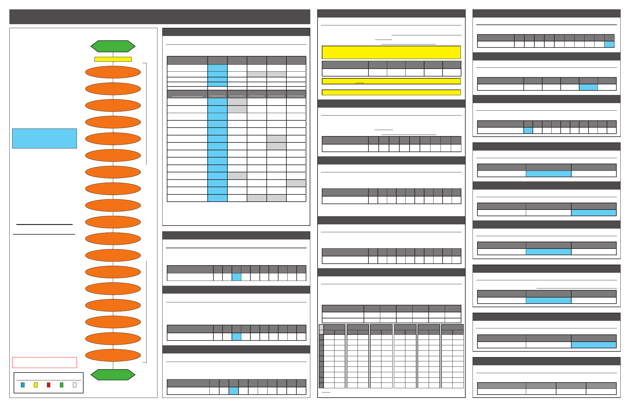
super-tuner
flow chart
CUSTOM programmiNG
This ESC software features Novak’s
Super-Tuner programming interface
with numerous ESC parameters that
can be customized to fine-tune the
ESC’s feel & response to your liking.
The flow chart and the descriptions
to the right show the order of the
different parameters and how they
effect the ESC’s feel or response.
One-Touch Programming should
be completed before customization
of parameters, as many of the
ESC parameters are based off
percentages of the trigger’s full-
throttle and full-brake position.
Note: ESC parameters do NOT default back
to the factory settings when the One-Touch
Programming is performed.
THE ESC PARAMETERS LISTED
IN BOLD IN THE TABLES TO
THE RIGHT ARE THE DEFAULT
SETTINGS FOR PROFILE #1
The sequence that the status LEDs
of the ESC goes through in the
Super-Tuner software is easier
than ever to follow. Common ESC
parameters are grouped together,
and the LEDs also light up in order
from left to right on the ESC.
The first adjustable item is the
ESC’s Throttle Profile, next comes
a group of 3 Braking adjustments,
then 5 Timing settings, followed by
4 Drive settings, and then finished
up with LiPo ON/OFF, Timing ON/
OFF, Thermal Protection ON/OFF,
and a motor test mode to check the
hall sensors & harness connections.
TO CHANGE PARAMETER SETTINGS:
1. CONNECT THE ESC TO A FULLY
CHARGED BATTERY PACK, A
RECIEVER, AND THE MOTOR’S
SENSOR HARNESS
2. SLIDE THE ESC’s ON/OFF
SWITCH TO ‘ON’ POSITION
3. WITH ESC AT NEUTRAL, PRESS
& HOLD SET BUTTON
Release ESC’s SET button once LEDs
are lit for the desired setting.
To skip a parameter, continue
to press & hold SET button until
desired parameter is reached.
4. SELECT PARAMETER VALUE
LED flashes to indicate active setting
(refer to tables at right). Quick press
& release SET button to select
desired setting.
5. PRESS & HOLD SET BUTTON TO
STORE NEW SELECTION
When SET button is pressed and
held for about 1 second,
the
new selection is stored in ESC’s
memory—Status LEDs will scroll across
to indicate ESC is exiting programming
& ESC returns to neutral.
There is no time constraint during
selection of custom parameters.
Note: ESC Parameter values are subject to
change due to ongoing development. Refer
to our web site for updated values and more
information on ESC parameters.
ESC STATUS LED ORDER:
BLUE YELLOW RED
GREEN WHITE
hall sensor test
#18 MOTOR SENSOR TEST
BLINKING BLUE LED
>>
This is a diagnostic test that checks the brushless motor’s sensors and harness.
To perform this test, refer to the ‘Motor Hall Sensor Test’ section on next page.
Motor Hall Sensor
A
B
C
LED Color:
BLUE
YELLOW
RED
TIMING level--10’s
#5 TIMING LEVEL 10’s SETTINGS
(1 of 5)
GREEN LED
The first digit, or “tens setting”, of the maximum number of degrees of Dynamic
Timing Advance applied to the motor.
This ESC has 0-55° of Dynamic Timing.
>> This setting adjusts the 1st digit of the maximum electronic motor
timing applied to the motor by ten degree increments.
Whenever the 10’s setting is modified, Timing is set to the even 10° increment
when the ESC exits programming. So, if you select setting #3, the timing is set
to 30°
(the 1’s value changes to zero until modified--this is how you get 10, 20, 30, & 40°).
Setting
(# of flashes)
1
2
3*
4*
5*
Timing Level
(degrees):
10
20
30
40
50
WARNING: DO NOT FREE-REV MOTOR TO CHECK TIMING SETTINGS
*Levels above 30° produce excessive heating & must be used with caution.
Physical motor timing should be set at/below 30° (
“N” on older Ballistic motors
)
TIMING level--1’s
#6 TIMING LEVEL 1’s SETTINGS
(1 of 9)
WHITE LED
The second digit, or “ones setting”, of the maximum number of degrees of
Dynamic Timing Advance applied to the motor.
>> This setting adjusts the 2nd digit of the maximum electronic motor
timing applied to the motor by one degree increments.
Setting
(# of flashes)
1
2
3
4
5
6
7
8
9
Timing Level
(degrees):
1
2
3
4
5
6
7
8
9
TIMING STart rPm
#7 TIMING START RPM POINT
(1 of 10)
BLUE & YELLOW LEDs
The RPM trip point at which Dynamic Timing Advance starts being applied.
>> Increasing this setting will increase the motor RPM at which the
electronic motor timing advancement begins coming on.
Setting
(# of flashes)
1
2
3
4
5
6
7
8
9 10
Start RPM
(in table)
:
1
2
3
4
5
6
7
8
9
10
Note: Selection chooses a line number from within the selected RPM Range Tables below. First
select RPM Table # (step #9), then select desired Start & Final RPM line numbers from table.
TIMING FINAL rPm
#8 TIMING FINAL RPM POINT
(1 of 10)
BLUE & RED LEDs
The RPM trip point at which Dynamic Timing Advance finishes being applied.
>> Increasing this setting will increase the motor RPM at which the
electronic motor timing advancement stops coming on.
Setting
(# of flashes)
1
2
3
4
5
6
7
8
9 10
Final RPM
(in table)
:
1
2
3
4
5
6
7
8
9
10
TIMING rPm RANGE
#9 TIMING RPM LOOK-UP TABLE
(1 of 6)
BLUE & GREEN LEDs
The speed control software’s available look-up tables of Timing RPM trip points
(start/final) at which Dynamic Timing Advance starts and ends being applied.
>> Changing this setting changes the table number that the ESC uses
to look-up Start & Final RPM trip points selected in steps #7 & 8 above.
Setting
(# of flashes)
1
2
3
4
5
6
RPM Range:
Table 1 Table 2 Table 3 Table 4 Table 5 Table 6
typical application-->
1S Racing SpecTiming Mod4
/
2wd General
/
SCT Open
/
S.Run 10.5
/
Lg.Track
Note: Within the selected RPM Range Table, the Start & Final RPMs (steps #7 & 8) are selected
separately from the same table but do not have to be the values across from each other in the table.
throttle profile
#1 THROTTLE PROFILE SELECTION
(1 of 5) BLUE-RED-WHITE LEDs
>> Increasing this setting changes the active Throttle Profile. Each
of the Thottle Profiles are independently adjustable once selected.
Profile
(# of flashes)
1
2
3
4
5
typical application-->
No-timing No-timing Modified Modified No-timing
“Blinky”
“Blinky”
Mild Timing Med.Timing
“Blinky”
Slick Tracks
High-Grip
Safe RPMs Lower RPMs Slick Tracks
(smoother)
(more aggressive) (less aggressive) (more aggressive) Reverse ON
ESC Parameter
def.setting def.setting def.setting def.setting def.setting
Drag Brake
3
5
3
3
3
Minimum Brake
3
5
3
3
3
Brake Frequency
3
3
3
3
3
Timing--10’s
1*
1*
1
1
1*
Timing--1’s
1**
1**
1**
1**
1**
Timing Start RPM
10*
10*
10
1
10*
Timing Final RPM
10*
10*
10
1
10*
RPM Range
4*
4*
4
4
4*
Drive Frequency
10
10
10
10
10
Dead Band
4
4
4
4
4
Minimum Drive
1
5
1
1
1
Reverse
1
1
1
1
2
Votage Cut-Off
2
2
2
2
2
Dynamic Timing
1
1
2
(ON)
2
(ON)
1
*Even though Dynamic Timing in turned OFF in Thorttle Profiles #1 & 2, the timing
settings can be adjusted. If Timing is turned ON, the selected values will be active.
**The 1’s Timing setting defaults to 0°, however if you go into the 1’s set-up mode
you will automatically change it to 1°, or setting #1, and will see the LED flash once.
Table 2
Start
Final
4000 10000
4500 10500
5000 11000
5500 11500
6000 12000
6500 12500
7000 13000
7500 13500
8000 14000
8500 14500
Table 3
Start
Final
9000 15000
9500 16000
10000 17000
10500 18000
11000 19000
11500 20000
12000 21000
12500 22000
13000 23000
13500 24000
Table 4
Start
Final
10000 20000
11000 21000
12000 22000
13000 23000
14000 24000
15000 25000
16000 26000
17000 27000
18000 28000
19000 29000
Table 5
Start
Final
21000 31000
22000 32000
23000 33000
24000 34000
25000 35000
26000 36000
27000 37000
28000 38000
29000 39000
30000 40000
Table 6
Start
Final
6000 16500
6500 18000
7000 19500
7500 21000
8000 22500
8500 24000
9000 25500
9500 26000
10000 27500
10500 29000
Table 1
Start
Final
1
1500 4000
2
1750 4500
3
2000 5000
4
2250 5500
5
2500 6000
6
2750 6500
7
3000 7000
8
3250 7500
9
3500 8000
10
3750 8500
DRIVE FREQUENCY
#10 DRIVE FREQUENCY SELECTION
(1 of 10)
BLUE & WHITE LEDS
>> Increasing this setting increases the Drive Frequency which makes the
throttle response feel smoother and more controllable.
Setting
(# of flashes)
1
2
3
4
5
6
7
8
9
10
Drive Freq.
(KHz)
:
8
10 12 14 16 21 23 26 32 36
dead band
#11 DEAD BAND SETTINGS
(1 of 5)
BLUE-YELLOW-RED LEDs
>> Increasing this setting increases the ‘free play’, or distance the transmitter’s
trigger must move from neutral before actual forward drive or braking begins.
Setting
(# of flashes)
1
2
3
4
5
Dead Band (%):
2
3
4
5
8
minimum drive
#12 MINIMUM DRIVE SETTINGS
(1 of 10) BLUE-YELLOW-GREEN LEDs
>> Increasing this setting starts forward drive at a stronger/higher level
(useful to minimize the trigger throw required before a heavier vehicles begins moving).
Setting
(# of flashes)
1
2
3
4
5
6
7
8
9 10
Minimum Drive (%):
0
1
2
3
4
6
8 10 12 15
reverse--on
/
off
#13 REVERSE SELECTION
(1 of 2)
BLUE-YELLOW-WHITE LEDs
>> Enables or disables the ESC’s reversing functionality.
OFF = Fwd/Brake only
.
Setting
(# of flashes)
1
2
Reverse:
OFF
ON
voltage cut-off--on
/
off
#14 LiPo CUT-OFF SELECTION
(1 of 2) BLUE-YELLOW-RED-GREEN LEDs
>> Enables or disables the ESC’s Smart Stop voltage cut-off circuitry.
Setting
(# of flashes)
1
2
Voltage Cut-Off Type:
OFF
(NiMH/NiCd)
LiPo
timing--on
/
off
#15 ELECTRONIC TIMING SELECTION
(1 of 2) YELLOW & RED LEDs
>> Enables or disables the ESC’s Dynamic Timing Advance features.
Setting
(# of flashes)
1
2
Dynamic Timing:
OFF
ON
data reset
#16 DEFAULT DATA RESET
YELLOW & GREEN LEDs
>> This feature resets the ESC’s adjustable parameters to factory default
values for all throttle profiles. Select setting #2 then Push & Hold to RESET.
Setting
(# of flashes)
1
2
Data Reset:
KEEP DATA
RESET ALL DATA
tHERMAL PROTECTION--on
/
off
#17 TEMP. OVERLOAD SELECTION
(1 of 2) YELLOW & WHITE LEDs
>> Enables or disables the ESC’s Temperature Overload Protection Circuitry.
Setting
(# of flashes)
1
2
Thermal Protection:
OFF
ON
@NEUTRAL
RED LED on solid
DRAG BRAKE
BLUE
THROTTLE PROFILE
BLUE-RED-WHITE
MIN. BRAKE
YELLOW
TIMING START RPM
BLUE & YELLOW
BRAKE FREQ.
RED
press & hold SET button
continue holding ESC’
s SET button to skip steps here
TIMING LEVEL--10’s
GREEN
TIMING LEVEL--1’s
WHITE
TIMING FINAL RPM
BLUE & RED
VOLTAGE CUT-OFF
BLUE-YELLOW-RED-GREEN
TIMING RPM RANGE
BLUE & GREEN
DRIVE FREQ.
BLUE & WHITE
DEAD BAND
BLUE-YELLOW-RED
MIN. DRIVE
BLUE-YELLOW-GREEN
REVERSE
BLUE-YELLOW-WHITE
TIMING ON/OFF
YELLOW & RED
DATA RESET
YELLOW & GREEN
THERMAL ON/OFF
YELLOW & WHITE
HALL SENSOR TEST
BLINKING BLUE
@NEUTRAL
RED LED on solid