Custom programming-crawling mode, Rock boost, Dead band – Novak Brushless Speed Control: Crusher Field Guide (Crawler Mode) --- Simple-Tuner Version ESC (4) User Manual
Page 3: Drive frequency, Minimum drive, Motor rotation, Voltage cut-off, Data reset, Hall sensor test
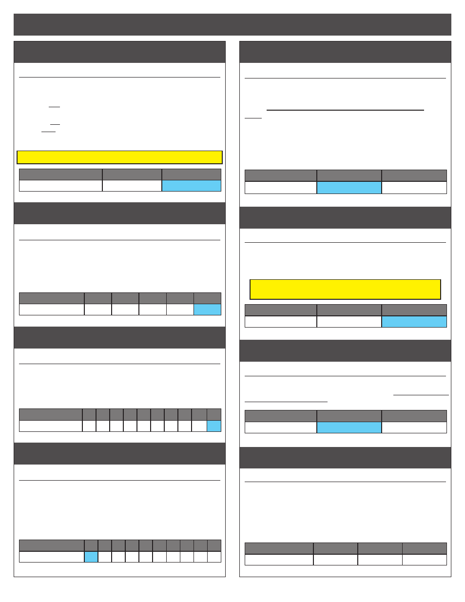
rOCK BOOST
#3 ROCK BOOST
GREEN LED
Changing this setting activates or deactivates ESC’s Boost Timing. This
feature is available with 2S LiPo and not with 3S or 4S LiPo packs.
>>When OFF, ESC’s throttle response is linear from neutral to full
throttle with no electronic motor timing advancement being applied.
>>When ON, ESC still has linear response throughout throttle
range, then when transmitter is held at full throttle, RPM Boost
Timing is engaged & ESC electronically advances the motor timing
for increased top speeds.
White LED will be ON when RPM Boost Timing is being applied
Setting
(# of flashes)
1
2
RPM Boost Timing:
OFF
ON
dead band
#4 DEAD BAND SETTINGS
(1 of 5)
BLUE & RED LEDs
The space between Minimum Brake and Minimum Drive, with Neutral
in the middle.
>> Increasing this setting increases amount of ‘free play’, or
distance the transmitter’s trigger must move before forward
drive or braking begins.
Setting
(# of flashes)
1
2
3
4
5
Dead Band (%):
2
3
4
5
8
drive frequency
#5 DRIVE FREQUENCY SETTINGS
(1 of 10) BLUE & GREEN LEDs
How the ESC’s throttle response feels with respect to the transmitter’s trig-
ger input.
>> Increasing the Drive Frequency makes the throttle response
feel smoother and more controllable.
Setting
(# of flashes)
1
2
3
4
5
6
7
8
9
10
Drive Freq.
(KHz)
:
8 10 12 14 16 21 23 26 32 36
minimum drive
#6 MINIMUM DRIVE SETTINGS
(1 of 10)
BLUE & WHITE LEDs
Amount of forward drive applied with first pulse of transmitter throttle
information.
>> Increasing this setting starts the forward drive at a stronger
level. This is useful to compensate for heavier vehicles to minimize
the amount of trigger throw required before effective drive is ap-
plied.
Setting
(# of flashes)
1
2
3
4
5
6
7
8
9 10
Minimum Drive (%):
0
1
2
3
4
6
8 10 12 15
motor rotation
#7 MOTOR ROTATION SELECTION
(1 of 2) BLUE-YELLOW-GREEN LEDs
>> Changing this setting changes the rotation direction of the
motor’s output/pinion shaft.
Counter-clockwise rotation is standard in most vehicles.
Note: Newer Novak Ballistic Crawler motors come factory-
timed to 0° mechanical timing and perform equally well in
both directions of rotation.
Older Ballistic Crawler motors MUST
have the motor’s mechanical timing adjusted to 0° for crawling or re-
verse rotation setups--Do this by aligning the sensor harness connector
opening of the motor’s back bearing cap directly in-line with the center
(Phase B) solder tab.
Setting
(# of flashes)
1
2
Rotation Direction:
CCW
Q
CW
P
voltage cut-off
#8 VOLTAGE CUT-OFF
(1 of 2)
BLUE-YELLOW-WHITE LEDs
>> Changing this setting enables or disables the built-in Auto-
Detect Smart Stop voltage cut-off circuitry, and also sets the
voltage cut-off point based on the number of cells in the ve-
hicle’s main battery pack.
DO NOT USE LiPo BATTERIES WITH THE ESC’S
VOLTAGE CUT-OFF CIRCUITRY TURNED OFF
Setting
(# of flashes)
1
2
Voltage Cut-Off Type:
OFF
(NiMH/NiCd)
LiPo
data reset
#9 DEFAULT DATA RESET
YELLOW & GREEN LEDs
>> This feature resets the ESC’s adjustable parameters to fac-
tory default values for all throttle profiles. Select setting #2
then Push & Hold to RESET.
Setting
(# of flashes)
1
2
Data Reset:
KEEP DATA
RESET ALL DATA
hall sensor test
#10 MOTOR SENSOR TEST
Blinking BLUE LED
>> This is a diagnostic feature that allows you to easily check
the functionality of your brushless motor’s hall effect sensors
& sensor harness and its connections at the speed control
and motor. Once activated, slowly rotate the motor’s output/
pinion shaft and the appropriate LED will light up if a signal
is received for its sensor in the motor. Refer to ‘MOTOR HALL
SENSOR TEST’ section on next page.
Motor Hall Sensor
A
B
C
LED Color:
BLUE
YELLOW
RED
Note: ESC Parameter values are subject to change due to ongoing development. Refer to our web site for updated values and more information on ESC parameters.
CUSTOM programmiNG-CRAWLING MODE