NORAC 4467BC+4B User Manual
Page 12
9
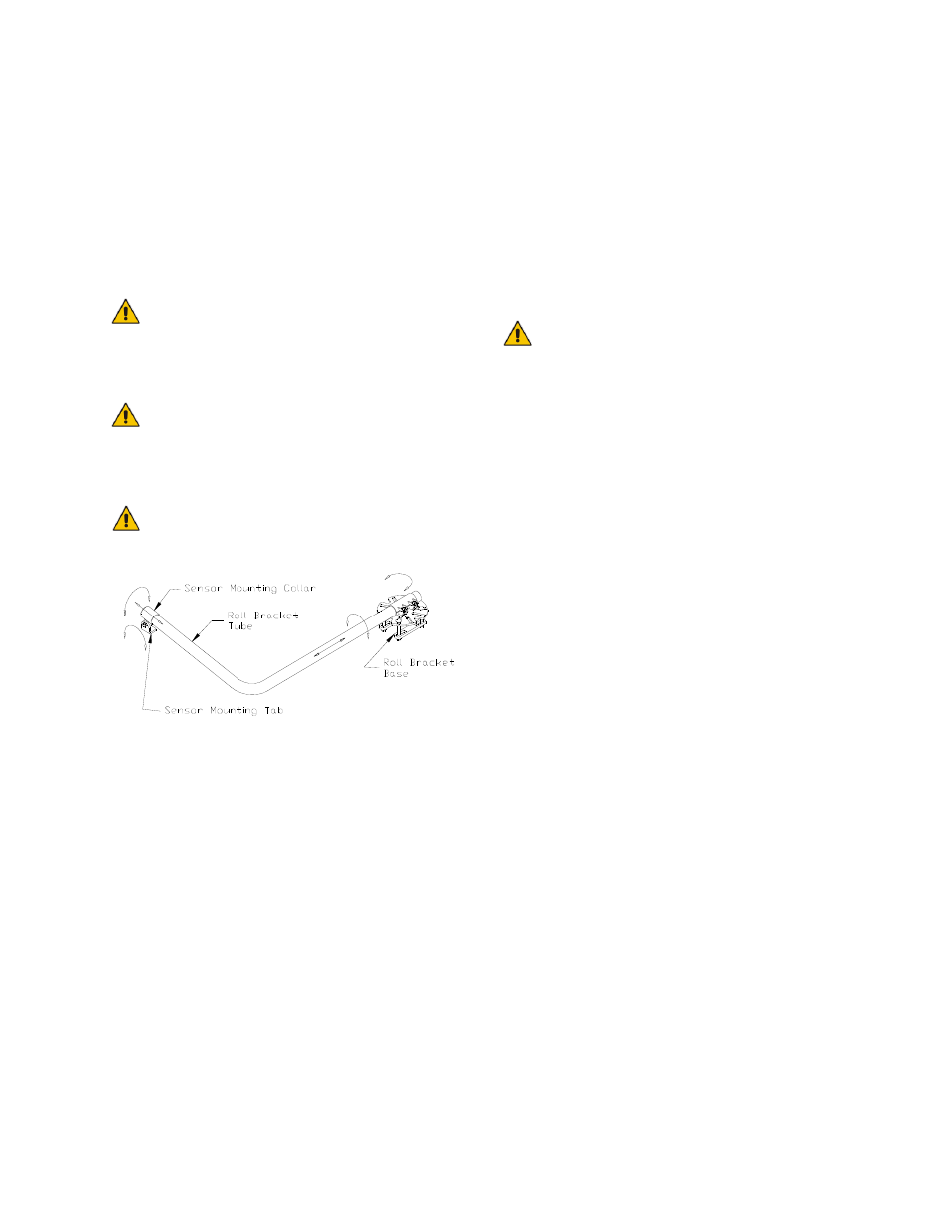
7. Assemble the roll sensor mounting
bracket as shown in Figure 7.
8. Install the roll sensor bracket on the T-
shaped black intermediate frame, as
shown in (Figure 6). The required
mounting hardware is included with the
bracket.
The bracket rod is designed to
slide in the bracket collar to
allow for sensor alignment
required in Step 9.
The sensor should be mounted
between the parallel lift arms and
the wheel in a position that will
not interfere with folding.
The sensor should not be behind
the wheel.
Figure 7: Roll Sensor Mounting
Bracket
9. Adjust the targets and sensor bracket
using a 4-foot level or a plumb line. The
goal of this step is to have the sensor
bracket and both targets in the proper
locations. The proper location of the
targets are as follows:
i) Spring target on the centerline of
the sensor.
ii) Frame target ½" to the left side of
the centerline
.
Ensure the sprayer is level AND
the booms are level when
installing the roll targets.
10. Hang a plumb line down the center of
the sensor mounting hole of the sensor
bracket. Check each target and
compare them to the proper location.
See Figure 6.
i) Ensure that both the roll and spring
targets are perpendicular to the
sensor.
ii) If both targets are to one side of the
plumb line, adjust the location of the
spring target bracket using the
adjustable ball and socket mount.
iii) The frame target can be adjusted by
sliding the bracket along the parallel
lift frame. This target should be
located ½" off the centerline.