1 hydraulic plumbing – NORAC UC4+BC+NT3 User Manual
Page 34
31
6.1 H
YDRAULIC
P
LUMBING
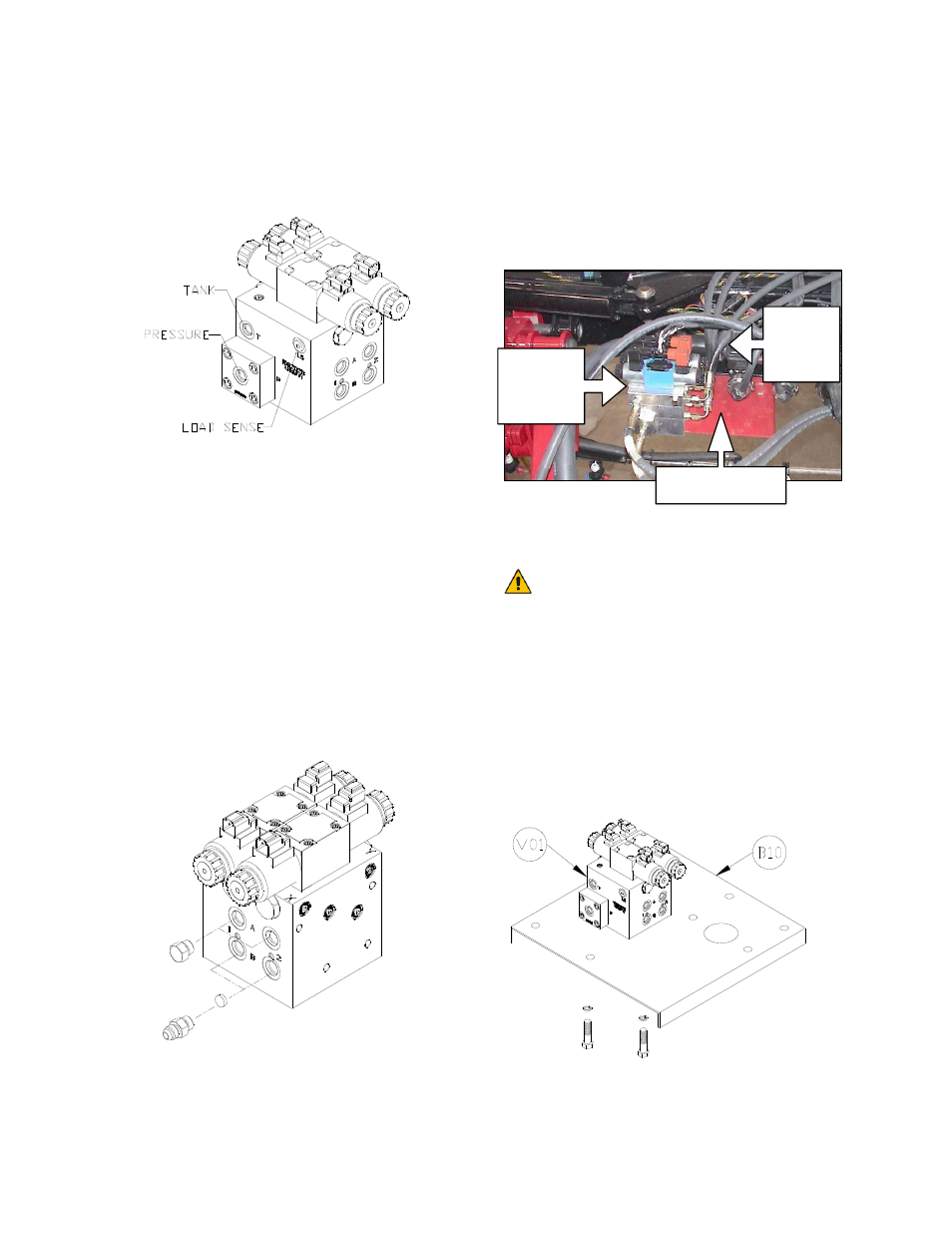
1. On a clean surface remove all plastic
plugs from the NORAC hydraulic valve
(V01) (Figure 25).
Figure 25: NORAC Valve Block
2. Install the orifices (F08) into the “B”
ports as shown in Figure 26.
3. Install the 6MB-6MJ fittings (F02) into
the “B” ports and tighten to 18 ft-lbs.
4. Install the 6MB-6MJ fittings (F02) in the
pressure (“P”) and tank (“T”) ports and
tighten to 18 ft-lbs.
5. Install the 6MBP plugs (F01) into the
“A” ports of the NORAC valve block
and tighten to 18 ft-lbs.
Figure 26: Valve Block Assembly
6. A valve mounting plate (B10) is
provided with 5/16” NC bolts, nuts and
washers. Mount the valve plate directly
under the spray nozzle valves (Figure
27).
Figure 27: Mounting Plate and Valve
Installation
You must ensure no hydraulic
components will interfere with
any sprayer parts or be pulled
tight at any time.
7. Mount the valve using the bolts and
washers in the location shown in
Figure 28. The bolts should thread
into the valve block at least 3/8”. The
valve mounting holes are drilled and
tapped to 3/8” NC-1” deep.
Figure 28: Valve Mounting Location
Spray
Nozzle
Valves
NORAC
Valve
Block
Mounting Plate