NORAC UC4+BC+JD6 User Manual
Page 28
25
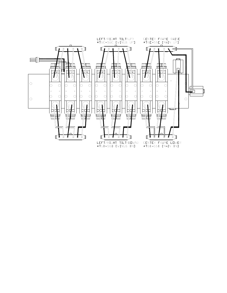
Figure 33: Sprayer Wiring Harness Identification
12. Locate the main John Deere wiring
harness at the rear of the sprayer near
the sprayer valve block. The sprayer
wiring harness identification is shown in
Figure 33.
13. Disconnect the JD harness connections
and connect in the junction cable (C12).
(Refer to Figure 33 and Figure 34.)
Center Frame:
Disconnect the 2 right most 6-pin
connectors of the JD harness.
Tee T6D-S6D of C12 into the
rearward connection. S6D is labeled
“Main Dn”.
Tee T6E-S6E of C12 into the
forward connection. S6E is labeled
“Main Up”.
Left and Right Booms:
Disconnect the 2 center 6-pin
connectors of the JD harness.
Tee T6B-S6B of C12 into the
rearward connection. S6B is labeled
“Wings Dn”.
Tee T6C-S6C of C12 into the
forward connection. S6C is labeled
“Wings Up”.
14. Connect the CAN Node cable (C02B)
to the 4-pin AMP plug on C01 (Figure
35).
15. Route the CAN Node cable (C02B) to
the roll sensors. Follow existing cables
and/or hydraulic lines.
- UC4.5-BC-AP3 (35 pages)
- UC4.5-BC-AS1 (22 pages)
- UC4.5-BC-CS1 (34 pages)
- UC4.5-BC-CS2 (35 pages)
- UC4.5-BC-CS3 (36 pages)
- UC4.5-BC-CS5 (42 pages)
- UC4.5-BC-EU1 (42 pages)
- UC4.5-BC-FC1 (29 pages)
- UC4.5-BC-FC2 (32 pages)
- UC4.5-BC-FT1 (32 pages)
- UC4.5-BC-FT3 (33 pages)
- UC4.5-BC-GN1 (38 pages)
- UC4.5-BC-GN2 Part 1 (20 pages)
- UC4.5-BC-GN2 Part 2 (11 pages)
- UC4.5-BC-GN6 (22 pages)
- UC4.5-BC-HD1 (32 pages)
- UC4.5-BC-HD3 Part 1 (36 pages)
- UC4.5-BC-HD3 Part 2 (7 pages)
- UC4.5-BC-HD4 Part 1 (45 pages)
- UC4.5-BC-HD4 Part 2 (7 pages)
- UC4.5-BC-HD5 Part 1 (31 pages)
- UC4.5-BC-HD5 Part 2 (10 pages)
- UC4.5-BC-HD7 (39 pages)
- UC4.5-BC-HD9 (24 pages)
- UC4.5-BC-JD6 (37 pages)
- UC4.5-BC-JD7 (42 pages)
- UC4.5-BC-JD8 (35 pages)
- UC4.5-BC-JD8A (46 pages)
- UC4.5-BC-JD11 (33 pages)
- UC4.5-BC-MC1 (31 pages)
- UC4.5-BC-MC2 (31 pages)
- UC4.5-BC-MS1 (32 pages)
- UC4.5-BC-NT3 (31 pages)
- UC4.5-BC-NT4 (35 pages)
- UC4.5-BC-PS1 (38 pages)
- UC4.5-BC-RA1 (42 pages)
- UC4.5-BC-RA2 (27 pages)
- UC4.5-BC-RG2 (38 pages)
- UC4.5-BC-RG4 (36 pages)
- UC4.5-BC-RG5 (35 pages)
- UC4.5-BC-SC2 (33 pages)
- UC4.5-BC-SC4 (28 pages)
- UC4.5-BC-SM2 (30 pages)
- UC4.5-BC-SS1 (34 pages)
- UC4.5-BC-TA1 (36 pages)