6 hydraulic installation, 1 valve assembly – NORAC UC4+BC+JD6 User Manual
Page 21
18
4.6 H
YDRAULIC
I
NSTALLATION
WARNING!
The hydraulic system creates very
high pressure. Before disconnecting
any hydraulic lines ensure all pressure
has been bled from the system.
When changing the boom hydraulic
hoses leave the booms in
TRANSPORT POSITION.
IMPORTANT:
Component failure due to oil
contamination is not covered under
the UC4+ System warranty. It is
recommended that a qualified
technician does the hydraulic
installation.
4.6.1 Valve Assembly
1. On a clean surface remove all plastic
plugs from the NORAC hydraulic Valve
(V01) (Figure 23).
2. Install the 6MB-6MOR (F09) fittings on
the "P" and "T" ports and tighten to 18
ft-lbs.
Figure 23: NORAC Valve Block
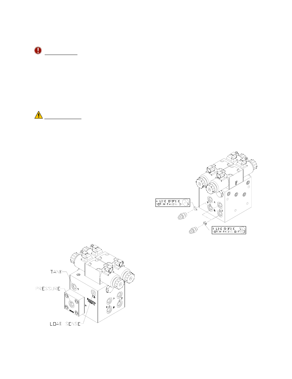
3. Install the 4MB-4MOR (F05) into the
"S" port and tighten to 11 ft-lbs.
4. Install the orifices (F10) into the "B"
port with the notch facing outward
as shown in Figure 24. An O-ring pick
can be used to ease installing the
orifices into their locations.
5. Install the orifices (F10) into the "A"
ports with the notch facing inward
as shown in Figure 24.
6. Install the 6MB-6MOR fittings (F09)
into the "A" and "B" ports and tighten to
18 ft-lbs.
Figure 24: Valve Block Assembly
7. Remove the plug from the Sense Line
Bleed port. Location is shown in
Figure 25. Gently tap the plug with a
hammer to loosen it before attempting
to remove it.
8. Remove the Sense Line Bleed Orifice
and discard. Figure 25.
9. Install the setscrew (F11) into the Sense
Line Bleed Orifice location. Ensure the
setscrew is threaded entirely into the
hole and tightened to 35-40 in-lbs to
ensure a tight seal.