NORAC UC4+BC+JD6 User Manual
Page 27
24
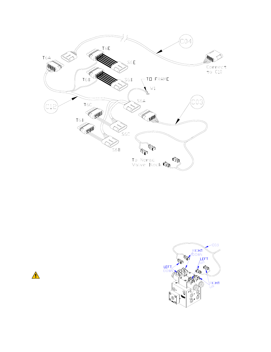
Figure 31: Cable Configurations: C03, C04, and C12
7. Connect the 6-pin Shroud on C04 to
T6A on the junction cable (C12)
(Figure 31).
8. Plug the 6-pin Tower on C03 into the
6-pin Shroud S6A on C12.
9. C12 has a screw terminal (W1) that
must be connected to the frame of the
sprayer. A good electrical connection
must exist between this terminal and
the frame. A good location is the bolt
holding the JD wiring harness next to
the large connector at the rear of the
sprayer frame.
W1 must be attached directly to
the sprayer frame NOT the
parallel linkage. Improper
ground can cause the UC4
System to switch from
AUTOMATIC mode into
MANUAL mode.
10. Install the 2-pin connectors from C03
onto each NORAC valve as shown in
Figure 32.
11. The connectors on the valve cable
(C03) are marked RIGHT UP, LEFT
UP, RIGHT DOWN and LEFT
DOWN. Cables labeled with UP go
on the same side as the hydraulic hoses.
Figure 32: Valve Cable Connections
- UC4.5-BC-AP3 (35 pages)
- UC4.5-BC-AS1 (22 pages)
- UC4.5-BC-CS1 (34 pages)
- UC4.5-BC-CS2 (35 pages)
- UC4.5-BC-CS3 (36 pages)
- UC4.5-BC-CS5 (42 pages)
- UC4.5-BC-EU1 (42 pages)
- UC4.5-BC-FC1 (29 pages)
- UC4.5-BC-FC2 (32 pages)
- UC4.5-BC-FT1 (32 pages)
- UC4.5-BC-FT3 (33 pages)
- UC4.5-BC-GN1 (38 pages)
- UC4.5-BC-GN2 Part 1 (20 pages)
- UC4.5-BC-GN2 Part 2 (11 pages)
- UC4.5-BC-GN6 (22 pages)
- UC4.5-BC-HD1 (32 pages)
- UC4.5-BC-HD3 Part 1 (36 pages)
- UC4.5-BC-HD3 Part 2 (7 pages)
- UC4.5-BC-HD4 Part 1 (45 pages)
- UC4.5-BC-HD4 Part 2 (7 pages)
- UC4.5-BC-HD5 Part 1 (31 pages)
- UC4.5-BC-HD5 Part 2 (10 pages)
- UC4.5-BC-HD7 (39 pages)
- UC4.5-BC-HD9 (24 pages)
- UC4.5-BC-JD6 (37 pages)
- UC4.5-BC-JD7 (42 pages)
- UC4.5-BC-JD8 (35 pages)
- UC4.5-BC-JD8A (46 pages)
- UC4.5-BC-JD11 (33 pages)
- UC4.5-BC-MC1 (31 pages)
- UC4.5-BC-MC2 (31 pages)
- UC4.5-BC-MS1 (32 pages)
- UC4.5-BC-NT3 (31 pages)
- UC4.5-BC-NT4 (35 pages)
- UC4.5-BC-PS1 (38 pages)
- UC4.5-BC-RA1 (42 pages)
- UC4.5-BC-RA2 (27 pages)
- UC4.5-BC-RG2 (38 pages)
- UC4.5-BC-RG4 (36 pages)
- UC4.5-BC-RG5 (35 pages)
- UC4.5-BC-SC2 (33 pages)
- UC4.5-BC-SC4 (28 pages)
- UC4.5-BC-SM2 (30 pages)
- UC4.5-BC-SS1 (34 pages)
- UC4.5-BC-TA1 (36 pages)