MUTEC MC-8.1 User Manual
Page 20
\\\\\\\\\\\\
AP P E N D I X
AP P E N D I X
AP P E N D I X
> > > > > > > > > > > > > > > > > > > > > > > > > > > > > > > > > > > > > > > > > > > > > > > > > > > > > > > > > > > > > > > > > > > >
> > > > > > > > > > > > > > > > > > > > > > > > > > > > > > > > > > > > > > > > > > > > > > > > > > > > > > > > > > > > > > > > > > > >
88
20
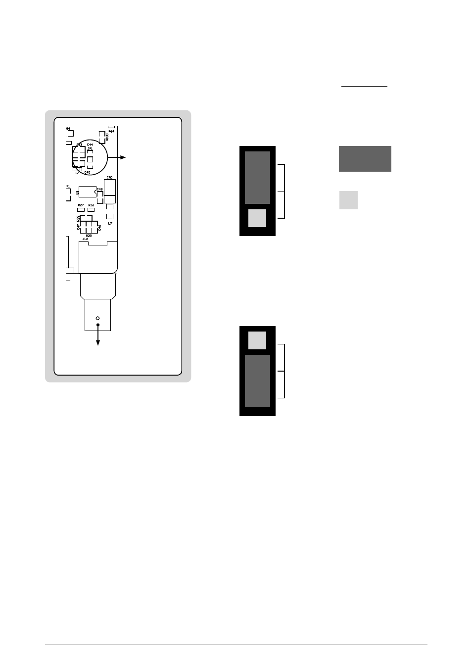
Switching-off the Termination of the Word Clock Input
CAUTION! Disconnect the unit from the mains before opening!
Remount the aluminium cover thoroughly before you attempt to operate
the unit!
When MC-8 or MC-8.1 is shipped, the BNC-based Word Clock input connec-
tor is terminated internally with 75 Ω. Therefore, one jumper is put on two
pins - Position 2 - of the 3-pin socket JP1.
When moving the jumper from position 2 to position 1, the input termina-
tion will be switched-off. Therefore, the MC-8 or MC-8.1 must be connected
in a chain, in which a device with terminated input follows. Otherwise
you need to use a BNC-T piece in combination with a 75 Ω BNC resistor for
terminating the MC’s input.
JP1
Jumper:
1
2
Free Pin:
Jumper on Position 2
= Termination
For additional information regarding this issue, please refer to page 11.
JP1
1
2
Jumper on Position 1
= no Terminaltion
Word Clock Termination
Termination
3-pin socket
JP1
WCLK
IN / OUT
at front