O p e rat i o n – MUTEC MC-8.1 User Manual
Page 17
\\\\\\\\\\\\
O P E RAT I O N
O P E RAT I O N
O P E RAT I O N
> > > > > > > > > > > > > > > > > > > > > > > > > > > > > > > > > > > > > > > > > > > > > > > > > > > > > > > > > > > > > > > > > > > >
> > > > > > > > > > > > > > > > > > > > > > > > > > > > > > > > > > > > > > > > > > > > > > > > > > > > > > > > > > > > > > > > > > > >
88
17
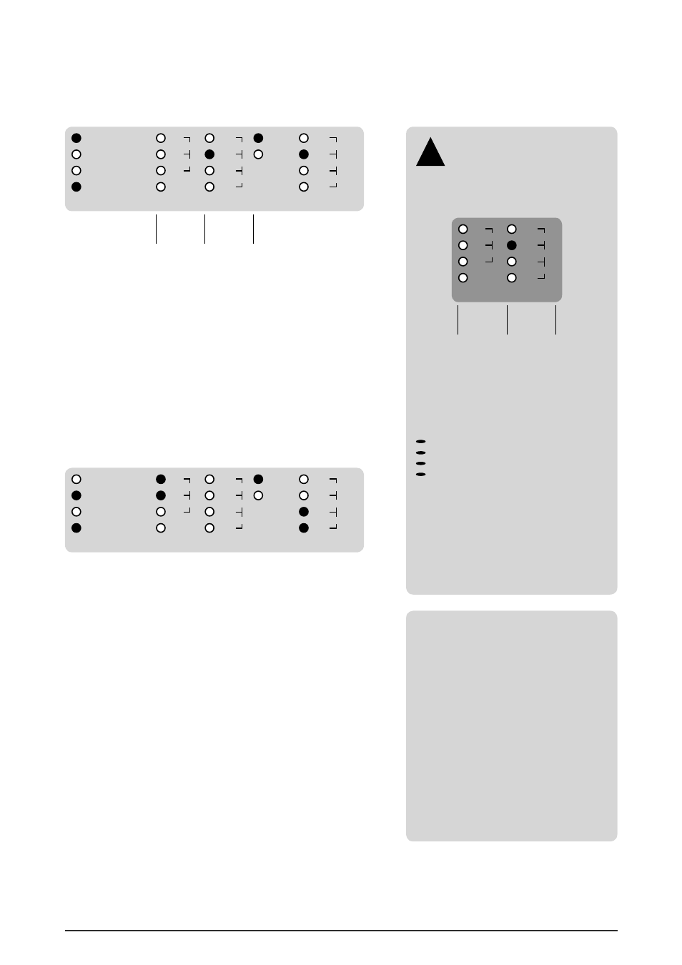
This setting enables to convert one input signal only (at input 1) to all four
outputs simultaneously, as described on page 16.
Now, the internal sampling rate converters (SRC) are activated additionally
and it is necessary to select a reference clock in the »REFERENCE« menu. In
the above displayed example, the internal clock generator is selected with
44.1kHz clock rate. That means, not depending on the clock rate of the
incoming signal, the outgoing signals will all carry the clock rate selected in
the »REFERENCE« menu.
In the »STATUS« menu the blue LED »LOCK« is lighting and shows that the
SRCs are locked to the internal clock generator.
In the »REF CLOCK
IN
« menu, the red LED »44.1« is lighting and thus shows
the clock rate of the reference clock, that means the internal clock generator,
which is here 44.1kHz.
Conversion from one Input to all four Outputs including the
Sampling Rate Conversion Function
REFERENCE
88.2
48.0
44.1
32.0
192.0
96.0
176.4
IN3
IN2
IN1
IN4
WCLK
AES11
IN1- 4 → OUT1- 4
IN1 → OUT1/2
IN2 → OUT3/4
IN1 → OUT1- 4
SRC
MODE
Internal
Clock
References
External
Clock
References
Conversion from two Inputs to two Output pairs including the
Sampling Rate Conversion Function
HOLD
LOCK
88.2
48.0
44.1
32.0
192.0
96.0
176.4
STATUS
REF CLOCK
IN
This setting enables to convert two individual input signals (at inputs 1+ 2)
to two output pairs, one output pair for every input signal, as described on
page 16.
In the above displayed example, Word Clock (WCLK) is selected as clock
reference for the internal SRCs.
In the »STATUS« menu the blue LED »LOCK« is lighting and shows that the
SRCs are locked to the externally supplied Word Clock signal.
In the »REF CLOCK
IN
« menu, the last two red LEDs in the row light in front
of »192.0« and thus show the clock rate of the externally supplied Word
Clock signal, which is 192.0kHz.
REFERENCE
88.2
48.0
44.1
32.0
192.0
96.0
176.4
IN3
IN2
IN1
IN4
WCLK
AES11
IN1- 4 → OUT1- 4
IN1 → OUT1/2
IN2 → OUT3/4
IN1 → OUT1- 4
SRC
MODE
HOLD
LOCK
88.2
48.0
44.1
32.0
192.0
96.0
176.4
STATUS
REF CLOCK
IN
References for Sampling Rate
Conversion
Your MC-8 or MC-8.1 allows to syn-
chronize the internal SRCs to various clock
reference signals. These possible references
can be selected in the »REFERENCE« menu:
!
REFERENCE
88.2
48.0
44.1
32.0
192.0
96.0
176.4
IN3
IN2
IN1
IN4
WCLK
AES11
Internal
Clock
References
External
Clock
References
Aligned to the clock reference type which
you want to supply, you must select the
corresponding clock reference within the
»REFERENCE« menu. Enter the »REFERENCE«
menu by pressing the »MENU« button and
press then the »SELECT« button repeatedly
to select the corresponding clock reference.
Selectable clock references are:
IN1-4 = Digital audio input no. 1, 2, 3 or 4
WCLK = Word Clock or Super Clock
AES11 = AES11 blank frame signal
32.0 -192.0 = Internal clock generator
When the external reference clock signal
can be locked by the internal PLL circuit, the
blue LED »LOCK« in the »STATUS« menu
will light constantly. The clock rate of the
selected clock source is then displayed in
the »REF CLOCK
IN
« menu. External clock
references can be supplied with all audio-
related clock frequencies between 32.0kHz
and 192.0kHz.
Function of Word Clock output when
activating the SRCs
When you are using the sampling rate
conversion function of your MC-8 or MC-8.1,
the selected reference clock will be output
through the Word Clock output at the rear
for synchronization of other devices.
If you have selected the internal clock gene-
rator as reference for the SRCs, the adjusted
clock rate will be output in phase with the
digital audio signals. If e.g. an incoming
digital audio or AES11 signal is selected as
reference, the MC-8 or MC-8.1 will extract
the clock out of this incoming reference
signal and will output it as low-jitter
reference clock at the Word Clock output.
The same applies of course for an incoming
Word Clock signal, selected as reference.