MUTEC MC-8.1 User Manual
Page 18
\\\\\\\\\\\\\\\\\\
A N H A N G
A N H A N G
A N H A N G
> > > > > > > > > > > > > > > > > > > > > > > > > > > > > > > > > > > > > > > > > > > > > > > > > > > > > > > > > > > > > > > > > > > >
> > > > > > > > > > > > > > > > > > > > > > > > > > > > > > > > > > > > > > > > > > > > > > > > > > > > > > > > > > > > > > > > > > > >
88
18
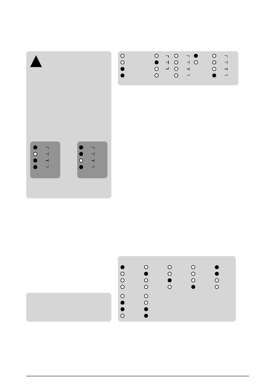
Conversion from four Inputs to four Outputs including the
Sampling Rate Conversion Function
This setting enables to convert four individual input signals to the four
outputs available, as described on page 16.
In the above displayed example, the digital audio input no. 2 (»IN2«) is
selected as clock reference for the internal SRCs.
In the »STATUS« menu the blue LED »LOCK« is lighting and shows that the
SRCs are locked to the externally supplied digital audio signal.
In the »REF CLOCK
IN
« menu, the last red LED lights in front of »88.2« and
thus shows the clock rate of the externally supplied digital audio signal,
which is then 88.2kHz.
STATUS Menu
This area displays different clock-related conditions of your MC-8 or MC-8.1.
There is no access for changing settings.
»LOCK«
This blue LED lights when the internal PLL circuit has detected the incoming
clock reference signal as valid, or is locked to the internal clock generator. If
the reference signal is unstable or lost, the »LOCK« LED does not light.
»HOLD«
This red LED lights when the external reference clock signal is interrupted
or lost. During this, the Word Clock output signal is continuously available
for stable and reliable synchronization of connected devices.
Furthermore, the HOLD function also enables to run the internal SRCs
interruption-free for continuous signal conversion in cases when the
externally supplied reference signal is interrupted or lost! Due to this, the
conversion function of the whole system is reliably secured.
REF CLOCK
IN
Menu
This area displays the clock rate of the incoming reference clock signal. The
following basis reference clock rates are supported and will be analyzed:
REFERENCE
88.2
48.0
44.1
32.0
192.0
96.0
176.4
IN3
IN2
IN1
IN4
WCLK
AES11
IN1- 4 → OUT1- 4
IN1 → OUT1/2
IN2 → OUT3/4
IN1 → OUT1- 4
SRC
MODE
HOLD
LOCK
88.2
48.0
44.1
32.0
192.0
96.0
176.4
STATUS
REF CLOCK
IN
Locking so-called
»Super Clocks«
Your MC-8 or MC-8.1 is able to lock
to so-called »Super Clock« (SCLK) refe-
rence signals. These clock signals are used
preferably for older digidesign ProTools™
MX systems. Specified are only two clock
rates, 11.2896MHz + 12.288MHz which are
the x256 multiples of the Word Clock rates
44.1kHz and 48.0kHz.
When locking to one of these Super Clocks,
the rate will be inverted displayed in the
»REF CLOCK
IN
« menu. Due to this, the LED
in front of the corresponding base clock
rate, that means Word Clock rate, does not
light while all other LEDs light (see exam-
ples below).
!
REF CLOCK
IN
88.2
48.0
44.1
32.0
192.0
96.0
176.4
Super Clock of
44.1kHz Word
Clock
Super Clock of
48.0kHz Word
Clock
REF CLOCK
IN
88.2
48.0
44.1
32.0
192.0
96.0
176.4
32.0kHz
44.1kHz
48.0kHz
88.2kHz
96.0kHz
176.4kHz
192.0kHz
Word Clock Rates
These indications are only available if
the internal PLL circuit is locked stably
to the external reference signal and the
corresponding blue LOCK LED lights
permanently.
Regarding the display of incoming Super Clock rates, please see above on
this page under „Locking so-called »Super Clocks«“.