Table 11: j34 usb connector, Table 11 – Maxim Integrated 78M6631 Evaluation Board User Manual
Page 16
78M6631 Evaluation Board User Manual
UM_6631_077
16
Rev 1
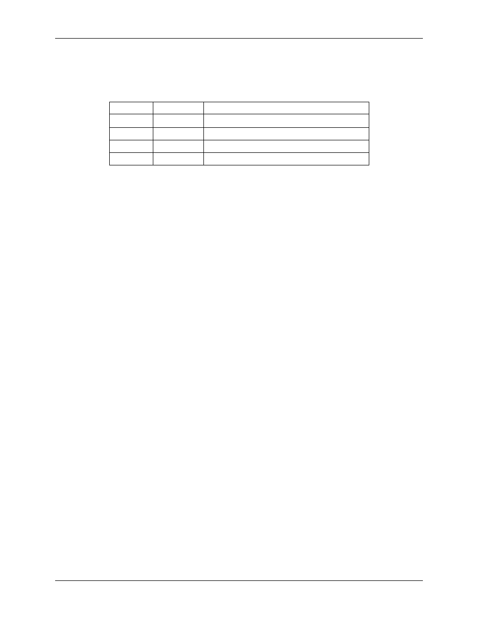
J34 USB Port Connection
The 78M6631 Evaluation Board is equipped with an USB interface. The interface allows the
communication to a host (PC etc.) and to provide supply power to the evaluation board.
Table 11: J34 USB Connector
Position
Signal
Description
1
USB5V
3.3VDC Supply
2
USBDM
General Purpose Digital I/O
3
USBDP
General Purpose Digital I/O
4, 5,6
USBGND
General Purpose Digital I/O
CT Burden Resistor Configuration
The 78M6631 Evaluation Board requires use of external CTs. Terminal blocks J1/J4, J5/J9, J10/J13,
provide the wiring connectors for these CTs. A burden resistor must be used with each CT. The CT’s
manufacturer provides the recommended burden resistor value. The 78M6631 Evaluation Board provides
a 12.4 Ω burden resistor for each pair of terminal blocks. Jumpers are provided for each pair of terminal
blocks for connection to these on-board burden resistors. Additionally, the jumpers provide connection to
V3P3 to establish a reference point for the CT.
If external burden resistors are used, install the following jumpers:
J3-1/J3-2
J8-1/J8-2
J12-1/J12-2
J2, J6, J11 have no jumpers.
If the on-board resistors are used, install the following jumpers:
J3-1/J3-2
J3-3/J3-4
J8-1/J8-2
J8-3/J8-4
J12-1/J12-2
J12-3/J12-4
J2-2/J2-3
J6-2/J6-3
J11-2/J11-3