Table 2: j32 evaluation board spi connector, Table 3: j27 ice connector, Table 4: j21 external battery connector/jumper – Maxim Integrated 78M6631 Evaluation Board User Manual
Page 14: Table 5: j36 isolated uart signal connector, Table 2, Table 3, Table 4, Table 5
78M6631 Evaluation Board User Manual
UM_6631_077
14
Rev 1
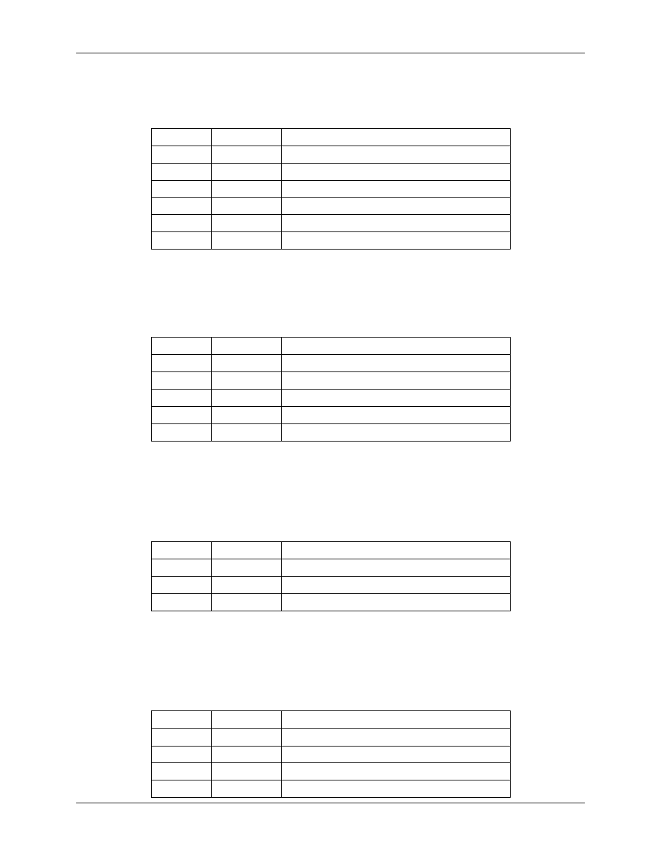
J32 SPI Connector
This connector allows the connection of the SPI interface. This connector is not isolated.
Table 2: J32 Evaluation Board SPI Connector
Position Signal
Description
1
V3P3D
3.3VDC Supply
2,4,6,8,10 GND
Ground
3
PCLK
SPI CLOCK (Input)
5
PSDI
SPI Data In (Input)
7
PSDO
SPI Data Out(Output)
9
PCSZ
SPI Slave Select (Input)
J27 In-Circuit Emulator (ICE) Connector
This connector allows the connection of the In-Circuit Emulator. Refer to Section 2.6 for ICE connector
adapters and ICE selection.
Table 3: J27 ICE Connector
Position Signal
Description
1
V3P3D
3.3VDC Supply
2
RXTX
DATA (Input/Output)
3
ERST
Emulator Reset (Input)
5
GND
Ground
6
ICEEN
ICE Port Enable (Input)
J21 External Battery Connector/Jumper
This Jumper/Connector allows the connection of the VBAT (78M6631 Battery Supply Input) to an external
battery backup. If an external battery in not required/not present, the jumper must be set in position 1-2 to
connect the VBAT input to the on-board 3.3VDC (V3P3) supply.
Table 4: J21 External Battery Connector/Jumper
Position Signal
Description
1
V3P3
3.3VDC Supply
2
VBAT
DATA (Input/Output)
3
GND
Ground
J36 Isolated UART Signal Connector
This connector allows an external transceiver to be connected or to provide test points to monitor the
UART signals. These signals are galvanically isolated from the 78M6631 circuitry. Jumper R35 is used to
disconnect the USBRX signal in case an external transceiver is used, in order to avoid contention.
Table 5: J36 Isolated UART signal Connector
Position Signal
Description
1
ISO5V
Isolated 5VDC Supply
2
URX
UART Rx
3
UTX
UART Tx
4
USBGND
Isolated Ground