Make Noise MATHS User Manual
Page 9
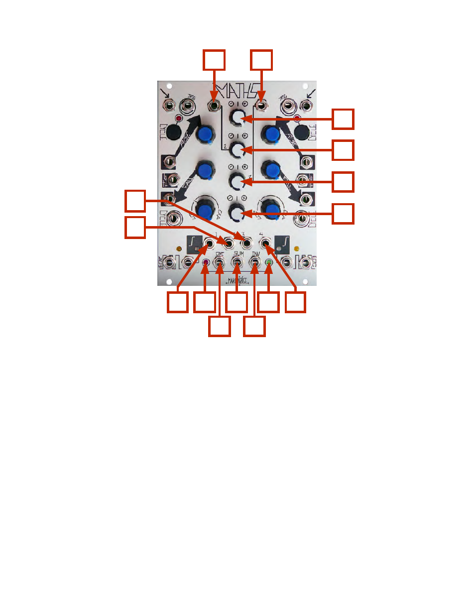
SUM and OR Bus
1. Signal IN Channel 2: Direct Coupled input to Attenuvertor and SUM/ OR Bus. Normalized to a +10V
reference for generation of voltage offsets. Input Range +/-10V
2. Signal IN Channel 3: Direct Coupled input to Attenuvertor and SUM/ OR Bus. Normalized to a +5V
reference for generation of voltage offsets. Input Range +/-10V
3. CH. 1 Attenuvertor Control: provides for scaling, attenuation and inversion of the signal being
processed or generated by CH. 1. Connected to CH. 1 Variable OUT and SUM/ OR Bus.
4. CH. 2 Attenuvertor Control: provides for scaling, attenuation, amplification and inversion of signal patch
to CH. 2 Signal IN. With no signal present it will control the level of the offset generated by CH. 2. Connected
to CH. 2 Variable OUT and SUM/ OR Bus..
5. CH. 3 Attenuvertor Control: provides for scaling, attenuation, amplification and inversion of signal patch
to CH. 3 Signal IN. With no signal present it will control the level of the offset generated by CH. 3. Connected
to CH. 3 Variable OUT and SUM/ OR Bus.
6. CH. 4 Attenuvertor Control: provides for scaling, attenuation and inversion of the signal being
processed or generated by CH. 4. Connected to CH. 4 Variable OUT and SUM/ OR Bus.
1
3
14
7
2
4
5
6
8
11
12
13
14
10
9