Nozzle-in-head waterboxes, Frame 3 and 5 marine waterboxes, Fig. 13 — nozzle arrangements 18 – Carrier Centrifugal Liquid Chiller 19EX User Manual
Page 18
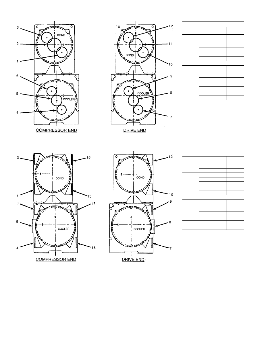
NOZZLE-IN-HEAD WATERBOXES
COOLER WATERBOX
Pass
In
Out
Arr.
Code
1
8
5
A
5
8
B
2
7
9
C
4
6
D
3
7
6
E
4
9
F
CONDENSER WATERBOX
Pass
In
Out
Arr.
Code
1
11
2
P
2
11
Q
2
10
12
R
1
3
S
3
10
3
T
1
12
U
NOTES:
1. Frame 5 condenser available in 1 and 2
pass only. Frame 3 in 2 and 3 pass only.
2. The vents for these waterboxes, located
in the covers are 1 in. FPT at the top of
each box, and the drains are 1 in. FPT, at
the bottom.
3. Victaulic connections are standard.
4. Flanged
waterbox
connections
are
optional.
FRAME 3 AND 5 MARINE WATERBOXES
COOLER WATERBOX
Pass
In
Out
Arr.
Code
1
8
5
A
5
8
B
2
7
9
C
4
6
D
16
17
G
3
7
6
E
4
9
F
CONDENSER WATERBOX
Pass
In
Out
Arr.
Code
2
10
12
R
1
3
S
13
15
Y
3
10
3
T
1
12
U
NOTES:
1. Frame 3 condenser available in 2 and 3
pass only. Frame 5 condenser available in
2 pass only.
2. The vents for these waterboxes are
1 in. FPT at the top of each box, and the
drains are 1 in. FPT, at the bottom.
3. Victaulic connections are standard.
4. Flanged
waterbox
connections
are
optional.
Fig. 13 — Nozzle Arrangements
18