LAARS Pennant PNCV (Sizes 500-2000) - Install and Operating Manual User Manual
Page 43
Pennant
(500-2000)
Page 43
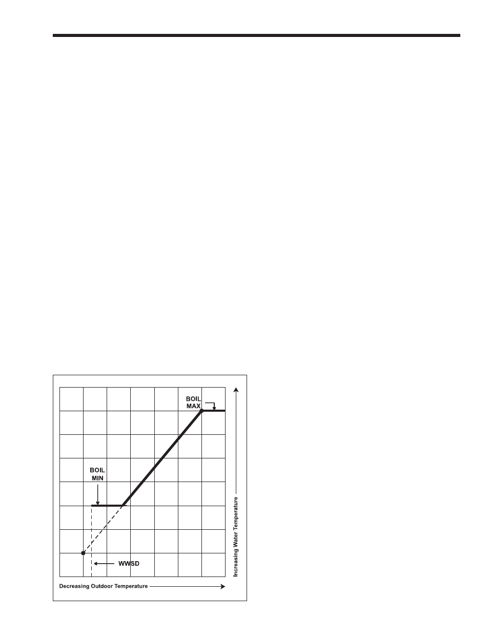
Figure 29. Temperature Control Min & Max.
stage. After the minimum time delay between stages
has expired, the control examines the control error to
determine when the next stage is to fire. The control
error is determined using PID logic.
Proportional compares the actual operating
sensor temperature to the boiler target temperature.
The colder the temperature, the sooner the next stage
is turned on.
Integral compares the actual operating sensor
temperature to the boiler target temperature over a
period of time.
Derivative determines how fast or slow the
operating sensor temperature is changing. If the
temperature is increasing slowly, the next stage is
turned on sooner. If the temperature is increasing
quickly, the next stage is turned on later, if at all.
Boiler Mass (BOIL MASS) – The boiler mass
setting allows the installer to adjust the control to the
thermal mass of different types of heat sources used.
The boiler mass setting automatically determines the
interstage differential, interstage delay on, interstage
delay off, minimum on time and minimum off time of
the stages when PID staging is used. A higher thermal
mass setting provides slower staging, while a lower
thermal mass setting provides faster staging. Pennant
boilers and water heaters are low-mass appliances, and
therefore, should be used with the lower thermal mass
setting. Set
BOIL MASS to “1”.
6.4.3 Boiler Minimum (BOIL MIN)
The minimum boiler setting (
BOIL MIN) is the
lowest water temperature that the control is allowed
to use as a target temperature. During mild conditions,
if the control calculates a target temperature that is
below this setting, the target temperature is adjusted to
at least the minimum setting. During this condition, if
the unit is operating, the MIN segment turns on in the
LCD while the target temperature or operating sensor
temperature is viewed. For Pennant units, this must be
set no lower than 120°F (49°C) to protect the unit
from condensing on the heat exchanger (see
Figure 29
).
6.4.4 Boiler Maximum (BOIL MAX)
The boiler maximum (
BOIL MAX) is the highest
water temperature that the control is allowed to use
as a target temperature. If the control does target
BOIL MAX, and the boiler outlet sensor is near the
BOIL MAX temperature, the MAX segment turns
on in the LCD while the target, inlet, outlet or supply
temperature is viewed (see
Figure 29
).
6.4.5 Boiler Target Temperature
The target temperature is determined from
the mode of operation. The control displays the
temperature that is currently trying to maintain at
the operating sensor as
BOIL TARGET in the View
menu. The operating sensor for modes 1, 3 and 4 is the
outlet sensor (on the Pennant). The operating sensor
for modes 2 and 5 is the supply sensor (in the system
or primary loop). If the control does not presently have
a requirement for heat, it displays “
- - -” in the LCD.
There is no target temperature generated in mode 6
(external controller mode).
6.4.6 Pump Operation
The pump terminals (Pmp Pmp) are energized
with 24 VAC to control a field supplied pump
contactor. During setpoint operation (modes 1 and 2),
the terminals are energized whenever there is a heat
demand. During dedicated DHW operation (mode
3), the terminals are energized whenever there is an
internal heat demand. During outdoor reset (modes 4
and 5), the terminals are energized whenever there is
either a heat demand and the control is not in Warm
Weather Shut Down (WWSD), or whenever there is
a setpoint demand. During WWSD, if the pump has
not operated at least once every 70 hours, the control
energizes the terminals for 10 seconds. This minimizes
the possibility of the pump seizing during a long
period of inactivity. During External Boiler Operation
(mode 6), the pump contact closes whenever there is a
heat demand.
Boiler Purge (PUMP DLY) – After a demand
is satisfied, the control continues to operate the pump
for a period of time. The length of time that the
pump continues to run is based on the pump delay
setting. Once the last stage of the control turns off,
the control keeps the pump contacts energized for
the time selected (between 0 and 10 minutes). When
OFF
is selected, there is no purging. When
ON
is