LAARS Pennant PNCV (Sizes 500-2000) - Install and Operating Manual User Manual
Page 24
LAARS Heating Systems
Page 24
SINGLE CIRCUIT CONNECTIONS
PUMP
HEATER
ONLY
W/O PUMP
WITH PUMP
TACO B&G
500
15
20
15 15
750
15
20
15 15
1000
20
25 (TACO) 30 (B&G) 15 15
1250
25
30
15 15
1500
25
30
15 15
1750
25
—
15 20
2000
25
—
20 20
Table 10. Electrical Data.
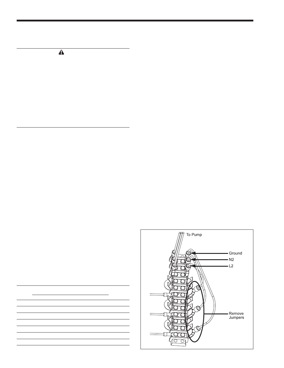
Figure 13. Removing Jumpers.
SECTION 5.
Electrical Connections
WARNING
The appliance must be electrically grounded in
accordance with the requirements of the authority
having jurisdiction or, in the absence of such
requirements, with the latest edition of the National
Electrical Code, ANSI/NFPA 70, in the U.S. and
with latest edition of CSA C22.1 Canadian Electrical
Code, Part 1, in Canada. Do not rely on the gas
or water piping to ground the metal parts of the
boiler. Plastic pipe or dielectric unions may isolate
the boiler electrically. Service and maintenance
personnel, who work on or around the boiler, may
be standing on wet floors and could be electrocuted
by an ungrounded boiler.
5.1 Main Power
Single pole switches, including those of safety
controls and protective devices must not be wired in a
grounded line.
All electrical connections are made in the field
wiring terminal strip, which is located at the right side
of the appliance.
NOTE: All internal electrical components have been
prewired. No attempt should be made to connect
elec-trical wires to any other location except the wiring
box.
5.1.1 Power Circuits
All Pennant non-pump-mounted heaters require a
single 120-volt fused supply.
Pump-mounted Pennants models 500-1500 also
uses a single 120-volt fused supply and models 1750-
2000 use two 120-volt fused supplies.
The installer can change the pump mounted
single service heaters to use a separate circuit for the
pump, if desired. Instructions to make this change are
found in
Section 5.1.2
.
Pennant 500-1500 main power (L1, N1 &
Ground) shall be connected to the three wires (10
AWG) supplied. Over current protection ratings can be
found in
Table 10.
Pennant 1750-2000 will require two 120-volt
fused supplies. Heater circuit can be identified with
10AWG wires to include black, white and green (all
solid colors). Pump circuit can be identified with three
12AWG wires to include a black wire with a white
tracer (stripe), a white and green wire.
5.1.2 Pump Circuit
Conversion to separate pump circuit will
necessitate removing the three jumpers within
the internal wiring of the 120-volt portion of the
heater (see
Figure 13
). Only do this with the power
disconnected to the unit.
To rewire the pump circuit, bring in another
120-volt fused supply (L2, N2 & Ground). Connect
incoming power (L2) to the main power switch using
spade (fork) terminal. From the other side of the main
power switch connect to the main terminal block using
a ¼" female insulated quick connect. This will be
the same position where the jumper had terminated.
Connect N2 and Ground to the main terminal block
using ¼" female insulated quick connect (refer to
Figure 13
).
Ladder diagrams are shown in
Figures 16
through 18,
while wire diagrams are shown in
Figures
19 through 21.
5.2 Temperature Control
5.2.1 Temperature Control Description
The field wiring panel is located on the right side
of the Pennant (shown in
Figure 14
). The following
components are connected to the field wiring panel:
Temperature sensor: The sensor supplied loose
with the Pennant is installed in the piping or tank,