LAARS Pennant PNCV (Sizes 500-2000) - Install and Operating Manual User Manual
Page 14
LAARS Heating Systems
Page 14
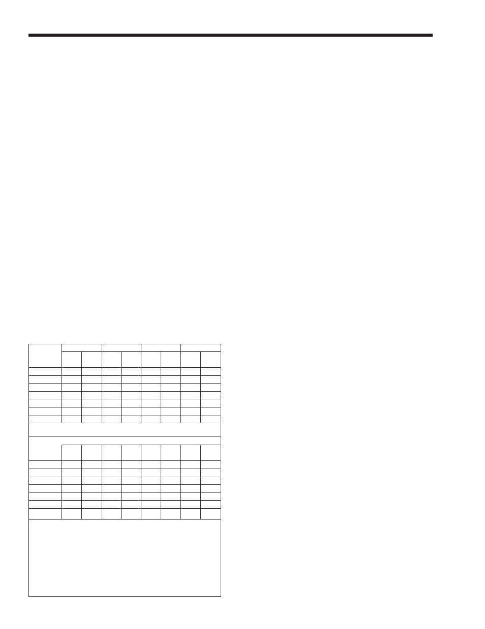
20°F 25°F 30°F 35°F
SIZE
flow
H/L
flow
H/L
flow
H/L
flow
H/L
gpm feet gpm feet gpm feet gpm feet
500
43 1.7 34 1.1 28 0.9 24 0.7
750
64 3.3 51 2.3 43 1.7 36 1.2
1000
85 5.0 68 3.6 57 3.1 49 2.2
1250
106 8.1 85 6.1 71 4.7 61 3.4
1500
128 10.0 102 7.2 85 5.5 73 4.2
1750
N/R N/R 119 10.5 99 8.4 85 5.8
2000
N/R N/R 136 12.5 113 10.4 97 8.3
Metric Equivalent
11°C 14°C 17°C 19°C
SIZE
flow
H/L
flow
H/L
flow
H/L
flow
H/L
lpm m lpm m lpm m lpm m
500 161 0.5 129 0.3 107 0.3 92 0.2
750 241 1.0 193 0.7 161 0.5 138 0.4
1000 321 1.5 257 1.1 214 0.9 184 0.7
1250 401 2.5 322 1.9 269 1.4 231 1.0
1500 483 3.0 386 2.2 322 1.7 276 1.3
1750
N/R N/R 451 3.2 375 2.6 322 1.8
2000 N/R N/R 515 3.8 429 3.2 368 2.5
Notes: gpm = gallons per minute, lpm = liters per minute,
H/L = headloss, ft = headloss in feet, m = headloss in meters.
Maximum temperature rise is 35°F (19°C), as shown.
Headloss is for boiler’s heat exchanger only.
N/R = not recommended.
Table 8. Water Flow Requirements - PNCH.
SECTION 4A.
Water Connections —
Pennant Boiler
4A.1 Heating System Piping:
Hot Supply Connections — Boiler
NOTE: This appliance must be installed in a closed
pressure system with a minimum of 12 psi (82.7kPa)
static pressure at the boiler.
Hot water piping should be supported by suitable
hangers or floor stands. Do not support piping with
this appliance. Due to expansion and contraction of
copper pipe, consideration should be given to the type
of hangers used. Rigid hangers may transmit noise
through the system resulting from the piping sliding in
the hangers. It is recommended that padding be used
when rigid hangers are installed. Maintain 1" clearance
to combustibles for hot water pipes.
Pipe the discharge of the relief valve (full size)
to a drain or in a manner to prevent injury in the event
of pressure relief. Install an air purger, an air vent,
a diaphragm-type expansion tank, and a hydronic
flow check in the system supply loop. Minimum fill
pressure must be 12psig (82.7kPa). Install shutoff
valves where required by code.
Suggested piping diagrams are shown in
Figures
4 through 8.
These diagrams are meant only as a guide.
Components required by local codes must be properly
installed.
Note the recommended location of the
temperature sensor on the diagrams; you must provide
a location for the additional sensor shipped with the
Pennant. This sensor may be strapped onto pipe from
1" to 4" diameter, or inserted into an immersion well.
4A.2 Cold Water Make-Up — Boiler
1. Connect the cold water supply to the inlet
connection of an automatic fill valve.
2. Install a suitable back flow preventer between the
automatic fill valve and the cold water supply.
3. Install shut off valves where required.
NOTE: The boiler, when used in connection with a
refrigeration system, must be installed so the chilled
medium is piped in parallel with the boiler with
appropriate valves to prevent the chilled medium from
entering the boiler.
The boiler piping system of a hot water heating
boiler connected to heating coils located in air
handling appliances where they may be exposed to
refrigerated air circulation must be equipped with flow
control valves or other automatic means to prevent
gravity circulation of the boiler water during the
cooling cycle.
A boiler installed above radiation level, or as
required by the authority having jurisdiction, must be
provided with a low water cutoff device either as a part
of the boiler or at the time of boiler installation.
4A.3 Water Flow Requirements — Boiler
A hydronic heating (closed loop) application
re-circulates the same fluid in the piping system. As a
result, no new minerals or oxygen is introduced into
the system. To ensure a proper operating temperature
leading to long boiler life, a flow rate has been
established based on the fluid temperature rise for this
specific size boiler.
Pump-mounted boilers can be ordered for use in
primary secondary piping systems. The pumps used
are sized for the headloss through the heater, plus 30
feet (9.1m) of full-sized piping (same size as boiler
outlet) and a normal number of fittings.
Table 8
specifies water flow rates for boilers,
which will enable the user to size a pump. The
headloss shown is for the heater only, and the user
will need to add the headloss of the system piping to
properly size the pump.
The minimum inlet water temperature for the
Pennant is 120°F (49°C) to avoid condensing on the
copper coils.