0 powering the controller for the first time, 0 input connections, 4 normally open input device - global unlock – Keri Systems EntraGuard Gold Quick Reference User Manual
Page 2: 0 output connections, 1 lock relay – fail-safe, 2 lock relay – fail-secure, 3 alarm out
P/N 01801-003 Rev. A
4.0
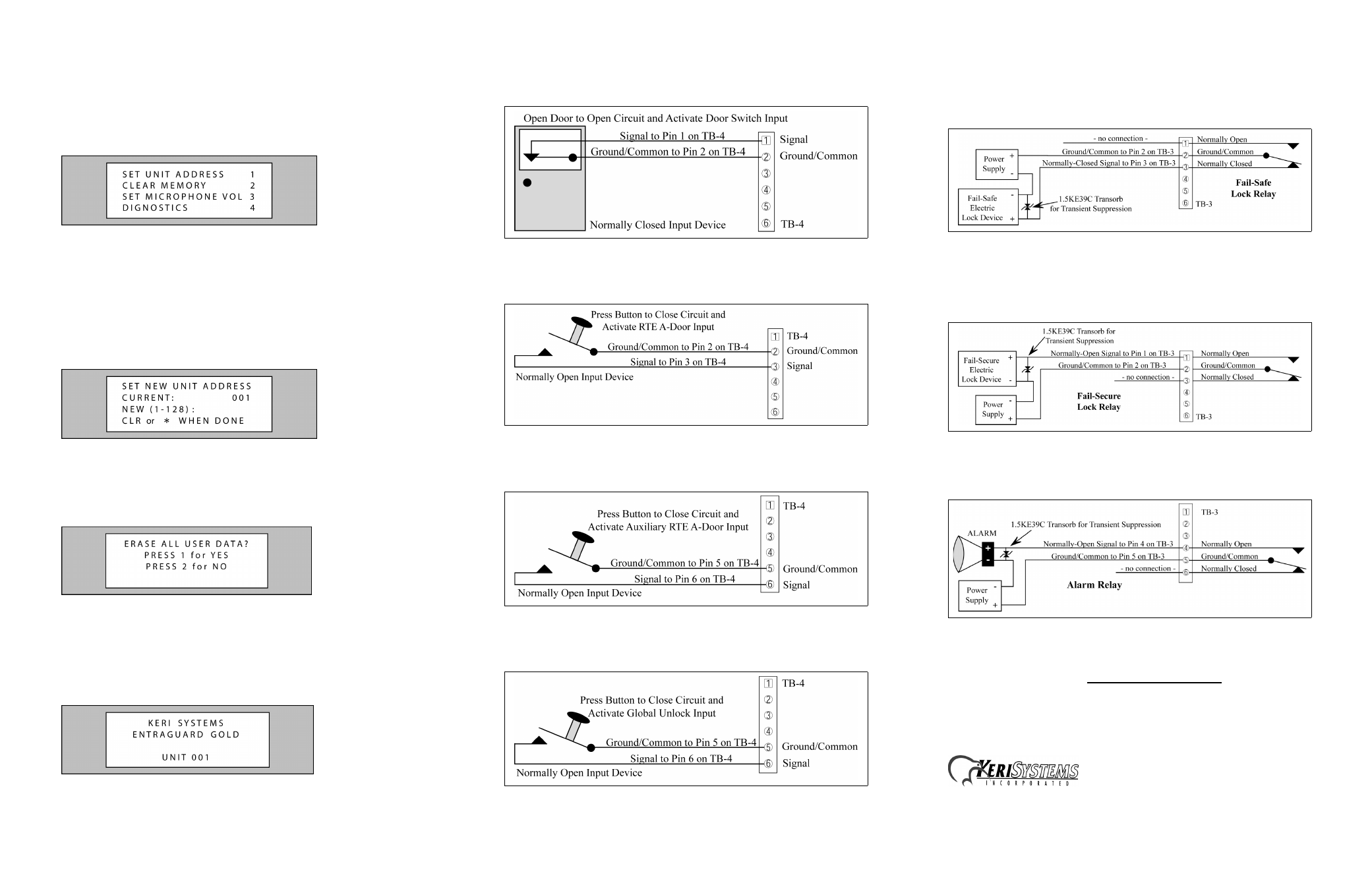
Powering the controller for the first time:
Power on the controller.
1.Make sure the controller’s power is off.
2.Hold the S1 button down and turn the controller's power on. The controller will beep once,
indicating the controller’s firmware is ready for programming.
3.Release the S1 button. The LCD on the front panel will display the Reset Menu (see Figure
3). From this menu you may perform different tasks such as set the controller’s address,
clear the controllers’ memory, set the microphone gain, and check diagnostics.
Figure 3: Reset Menu
Set the controller’s address.
1.From the Reset Menu, select number 1 on the controller keypad. The LCD will display the
Set Unit Address Menu (see Figure 4) showing the current default address of the controller.
If this is a master unit, it must be set to address 1. If it is a slave unit (an EntraGuard Gold
controller may only be slave to another EntraGuard Gold unit), the address may be set to any
number from 2-128.
2.To change the address of the controller, enter the new address on the keypad then select *.
3.If you have changed the address from the default address, the controller’s RAM will be
automatically reset. If the address has remained the same, you will need to manually reset
the controller’s RAM.
Figure 4: Set Unit Address Menu
Reset the controller’s RAM.
1.From the Reset Menu, select number 2 on the controller keypad. The LCD will display the
Clear Memory Menu (see Figure 5).
2.Select number 1 on the keypad to reset the RAM, or number 2 to cancel clear memory
command and return to the Reset Menu.
Figure 5: Clear Memory Menu
Update the access control network.
1.Once you have set the address and reset the controller’s RAM, a total update must be
performed on the system from the Doors program.
2.In the Doors program, click on the Update Net button. Make sure the Total Update Network
is set to Update and click on the Start button.
3.Once the update is completed, the EntraGuard controller’s LCD will display the default
message.
Figure 6: LCD Default Message
5.0
Input Connections
5.1
Normally Closed Input Device - Door Status Switch
Figure 7: Door Status Switch Input Device
5.2
Normally Open Input Device - Request To Exit (RTE)
Figure 8: Request To Exit Input Device
5.3
Normally Open Input Device - Auxiliary Request To Exit A-Door
Figure 9: Auxiliary Request To Exit A-Door Input Device
5.4
Normally Open Input Device - Global Unlock
Figure 10: Global Unlock Input Device
6.0
Output Connections
6.1
Lock Relay – Fail-Safe
In the event of a power failure at a door set up with a fail-safe lock relay, the door will automatically
unlock allowing people to exit through that door.
Figure 11: Fail-Safe Lock Relay
6.2
Lock Relay – Fail-Secure
In the event of a power failure at a door set up with a fail-secure lock relay, the door will
automatically lock and not allow entrance, but will continue to allow people to exit through that door.
Figure 12: Fail-Secure Lock Relay
6.3
Alarm Out
Figure 13: Alarm Out Relay
NOTE: If you are using the RS-232 port and a modem for communication between the master
controller and host computer, see the EntraGuard Gold Quick Start Guide (P/N 01801-001) for
instructions on how to install an external modem.
1530 Old Oakland Road, Suite 100
San Jose, CA 95112 USA
(800) 260-5265 (408) 451-2520 FAX (408) 441-0309
Web: http://www.kerisys.com E-mail: [email protected]