Keri Systems EP1501 User Manual
Page 3
Mercury Security © 2014
EP1501
DOC 10107-0036
REV 1.07
Page 3
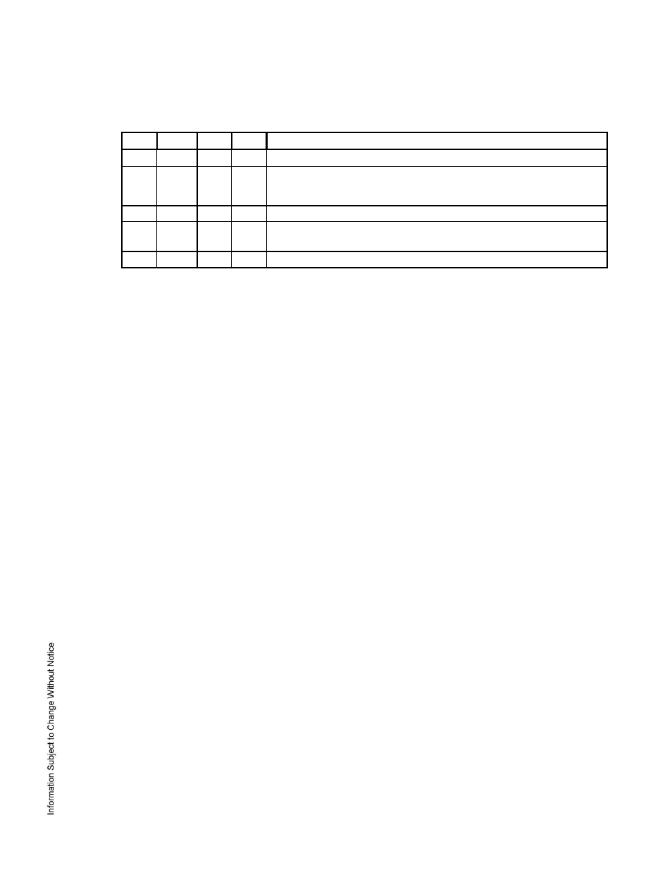
DIP Switches:
The four switches on S1 DIP switch configure the operating mode of the EP1501 processor. DIP
switches are read on power-up except where noted. Pressing switch S2 causes the EP1501 to reboot.
1
2
3
4
Definitions
OFF
OFF
OFF OFF Normal operating mode.
ON
X
X
X
After initialization, enable default User Name (admin) and
Password (password). The switch is read on the fly, no need to re-
boot. See IT Security section for additional information.
OFF
ON
X
OFF Use factory default communication parameters.
ON
ON
X
OFF Use OEM default communication parameters. Contact system
manufacture for details. See Bulk Erase section below.
X
X
ON
X
Disable TLS secure link. Switch is read only when logging on.
All other switch settings are unassigned and reserved for future use.
Factory Default Communication Parameters:
Network: static IP address: 192.168.0.251
Subnet Mask: 255.255.0.0
Default Gateway: 192.168.0.1
DNS Sever: 192.168.0.1
Host port: IP server, no encryption, port 3001, communication address: 0
4. Bulk Erase Configuration Memory:
The bulk erase function can be used for the following purposes:
Erase all configuration and cardholder database (sanitize board)
Update OEM default parameters after OEM code has been changed
Recover from database corruption causing EP1501 board to continuously reboot
If clearing the memory does not correct the initialization problem, contact technical support.
Bulk Erase Steps: Do not remove power during steps 1-8.
1. Set S1 DIP switches to: 1 & 2 "ON", 3 & 4 "OFF".
2. Apply power to the EP1501 board.
3. Watch for LEDs 1 & 2 and 3 & 4 to alternately flash at a 0.5 second rate.
4. Within 10 seconds of powering up, change switches 1 or 2 to "OFF". If these switches are not
changed, the EP1501 board will power up using the OEM default communication parameters.
5. LED 2 will flash indicating that the configuration memory is being erased.
6. Full memory erase takes up to 60 seconds.
7. When complete, only LEDs 1 & 4 will flash for 8 seconds.
8. The EP1501 board will reboot 8 seconds after LEDs 1 & 4 stop flashing (no LEDs are on during this
time).
5. Input Power:
The EP1501 is powered by one of two ways (jumper selected, J3):
Power is supplied via the Ethernet connection using PoE, fully compliant to IEEE 802.3af
Or local 12 Vdc power supply, TB4-3 (VIN), TB4-4 (GND)
6. Communication Wiring:
The EP1501 controller communicates to the host via the on-board 10-BaseT/100Base-TX Ethernet
interface.