Caution, Install outdoor unit, Side or bottom piping – Carrier 40QNQ User Manual
Page 7: Mounting on ground, Mounting on roof
7
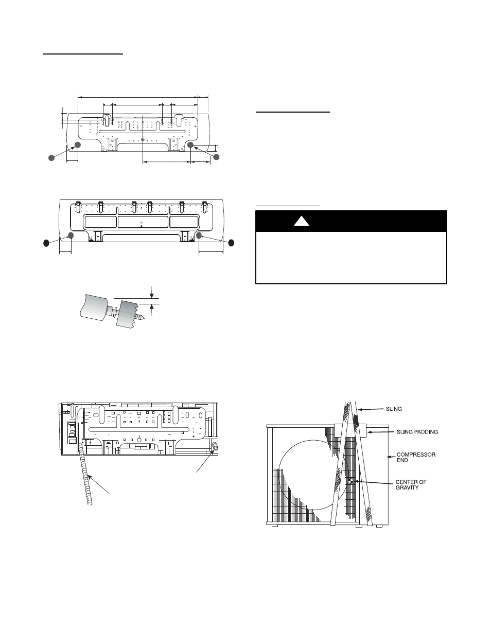
point A or B as shown in Fig. 12 or Fig. 13. Drill the hole at a
slope so that the outside end is 1/2 inch (13 mm) lower than inside
end to ensure optimal drainage. Refer to Fig. 14.
Side Or Bottom Piping
Remove the knockout in the unit and drill a 2--1/2 inch (63.5 mm)
hole where the pipe penetrates the structure using the guides given
above.
2.1"
(53.3)
14.9" (378.5)
3.5"
(88.9)
2.8"
(71.1)
2.8"
(71.1)
B
5.1”
(129.5)
13.8" (130.5)
A
2"
(50.8)
7.7" (195.6)
35.4” (899.2)
2.1"
(53.3)
1"
(25.4)
Note: Numbers in ( ) = mm
A09046
Fig. 12 -- 40QNC, QNQ018, 024 Mounting Plate
2"
5.1"
B
A
A09050
Fig. 13 -- 40QNC, QNQ030, 036 Mounting Plate
1/2 in. (13 mm)
Min.
INDOOR
OUTDOOR
A07371
Fig. 14 -- Drill Hole at Slope
4. Relocate drain connection if necessary -- Determine if the
installation requires a left or a right hand drain exit and relo-
cate the drain hose if necessary as shown in Fig. 15.
Drain Hose
Drain Cap
A08362
Fig. 15 -- Drain Hose and Cap Location
NOTE: If the condensate pump accessory is to be used, the drain
hose can be cut to provide space for the space for the condensate
pump reservoir in the back of the unit. The reservoir must be
installed at this time. Please refer to installation instructions
provided with the condensate pump accessory.
5. Place unit on a clean surface until you are ready to connect
the piping and wiring.
INSTALL OUTDOOR UNIT
The outdoor units can be installed on the ground, on the roof, or
mounted on a wall.
NOTE: Install the unit so that the coil does not face into
prevailing winds. If this is not possible and constant wind winds
above 25 mph are expected, use accessory wind baffle. See
installation instructions provided with accessory kit. Wind baffles
should also be used on all units with accessory low ambient
temperature control.
Mounting on Ground
1. Mount unit on a solid level concrete pad.
2. If a heat pump is being installed, use a field-- provided snow
stand or ice rack where prolonged subfreezing temperatures
or heavy snow occurs.
3. Position unit so water or ice from roof does not fall directly
onto unit.
4. On cooling only units, an accessory stacking kit can be used
when units are to be stacked. See installation instructions
provided with the accessory kit.
Mounting on Roof
PERSONAL
INJURY
AND/OR
EQUIPMENT
DAMAGE HAZARD
Failure to follow this caution may result in personal injury
and / or equipment damage.
Be sure unit panels are securely in place prior to rigging.
CAUTION
!
1. Rig the unit. Keep the unit upright and lift using a sling.
Use cardboard or padding under the sling, and spreader bars
to prevent sling damage to the unit. See Fig 16. See Fig. 2
for center of gravity reference
2. Mount unit on a solid concrete pad or platform.
3. Isolate unit and piping from structure
4. If a heat pump is being installed, use a field-- provided snow
stand or ice rack where prolonged subfreezing temperatures
or heavy snow occurs.
5. On cooling only units, an accessory stacking kit can be used
when units are to be stacked. See installation instructions
provided with accessory kit.
A07396
Fig. 16 -- Lifting Unit with Sling