Control wiring – Carrier 40QNQ User Manual
Page 10
10
Control Wiring
The control circuit is 24 volts AC (minimum 40VA) supplied from
the indoor unit.
1. Make sure you have enough control wires to cover the dis-
tance between the indoor and outdoor unit.
2. Route one end of the control wiring through the opening
provided in the unit side panel and connect to the control
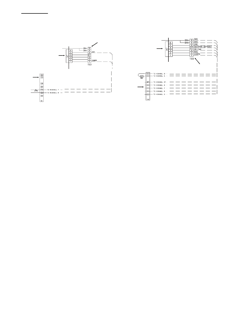
terminal strip using either Fig. 21 for 38HDF units and Fig.
22 for 38QRF units.
Outdoor
Terminal
Board
Indoor
Board
Indoor
Terminal
Board
Outdoor
Terminal
Board
Indoor
Board
Indoor
Terminal
Board
A09508
Fig. 22 -- 38HDF Control Terminal Strip
Outdoor
Terminal
Board
Indoor
Board
Indoor
Terminal
Board
Outdoor
Terminal
Board
Indoor
Board
Indoor
Terminal
Board
A09509
Fig. 23 -- 38QRF Control Terminal Strip
NOTE: Use No. 18 AWG color--coded, insulated (35_C minimum) wire. If the distance between the indoor and outdoor unit is greater than
100 ft. (30.5 m), as measured along the control voltage wires, use No. 16 AWG color--coded wire to avoid excessive voltage drop.