Carrier 40QNQ User Manual
Page 11
11
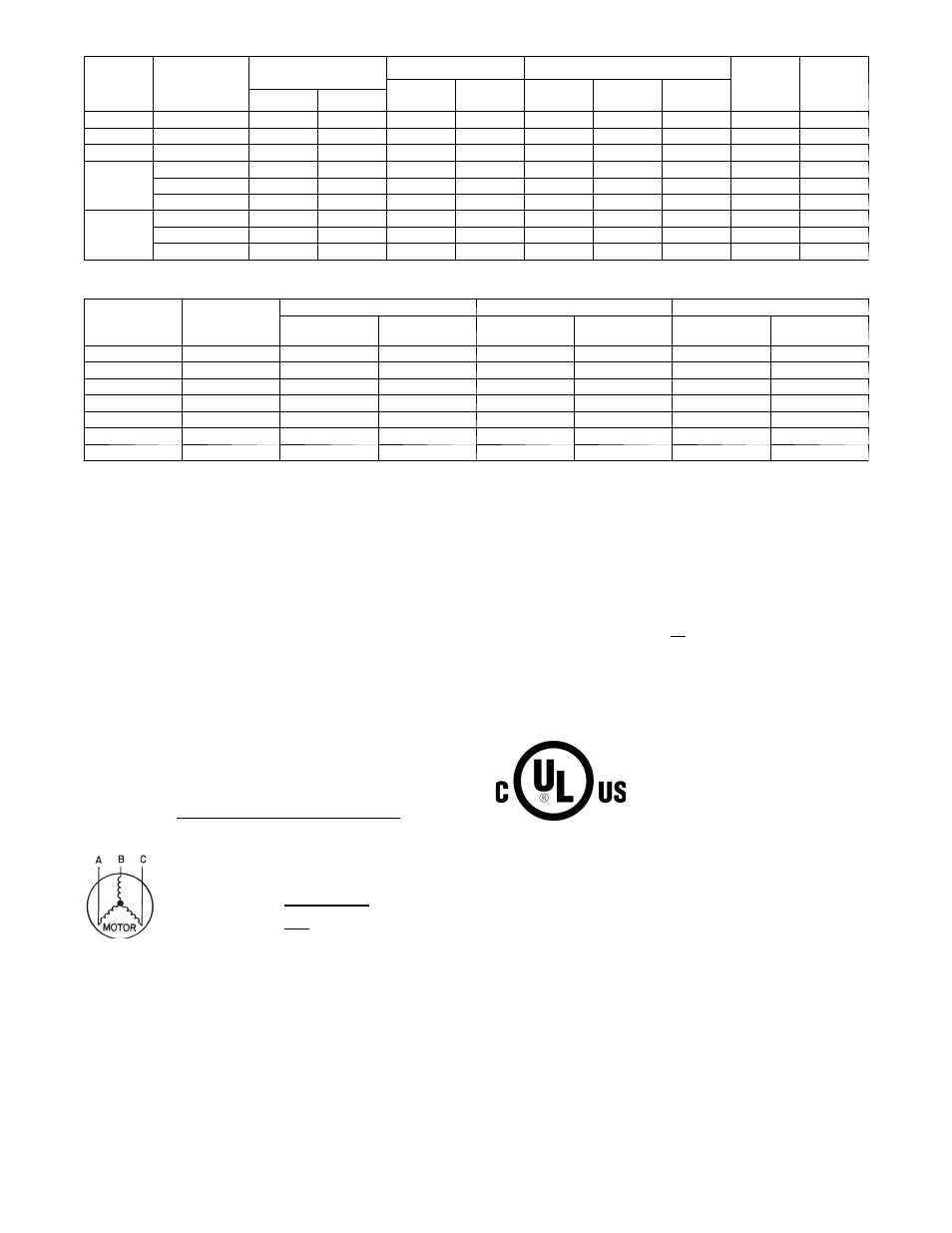
Table 10 – 38HDF / 38QRF Electrical Data
38HDF /
38QRF
UNIT
SIZE
V---PH---Hz
VOLTAGE RANGE*
COMPRESSOR
OUTDOOR FAN MOTOR
MIN CKT
AMPS
FUSE/
HACR
BKR
AMPS
RLA
LRA
FLA
NEC Hp
kW Out
Min
Max
018
208/230---1---60
187
253
9.0
48.0
0.80
0.125
0.09
12.1
20
024
208/230---1---60
187
253
12.8
58.3
0.80
0.125
0.09
16.8
25
030
208/230---1---60
187
253
14.1
73.0
1.50
0.25
0.19
18.4
30
035
208/230---1---60
187
253
16.7
79.0
1.50
0.25
0.19
22.3
35
208/230---3---60
187
253
10.4
79.0
1.50
0.25
0.19
14.5
20
460---3---60
414
506
5.8
79.0
0.80
0.25
0.19
8.7
15
036
208/230---1---60
187
253
17.9
112.0
1.45
0.25
0.19
23.8
40
208/230---3---60
187
253
13.2
88.0
1.45
0.25
0.19
18.0
30
460---3---60
414
506
6.0
44.0
0.80
0.25
0.19
8.3
15
Table 11 – 40QNC, QNQ Fan Coil Electrical Data
UNIT SIZE
V---PH---Hz
VOLTAGE RANGE*
FAN
POWER
Min
Max
FLA
Motor Power
(Watts)
MIN CKT
AMPS
FUSE/CKT
BKR AMPS
40QNC01824
208/230---1---60
187
253
0.38
64
0.48
15
40QNC030
208/230---1---60
187
253
0.38
74
0.48
15
40QNC036
208/230---1---60
187
253
0.44
74
0.55
15
40QNQ018
208/230---1---60
187
253
0.38
64
0.48
15
40QNQ024
208/230---1---60
187
253
0.38
64
0.48
15
40QNQ030
208/230---1---60
187
253
0.38
74
0.48
15
40QNQ036
208/230---1---60
187
253
0.44
74
0.55
15
LEGEND:
FLA --- Full Load Amps
LRA --- Locked Rotor Amps
NEC --- National Electrical Code
RLA --- Rated Load Amps (compressor)
* Permissible limits of the voltage range at which the unit will operate
satisfactorily
NOTES:
1. Control circuit is 24---V on all units and requires external power
source. Copper wire must be used from service disconnect to unit.
2. All motors/compressors contain internal overload protection.
3. In compliance with NEC (USA Standard) requirements for multimo-
tor and combination load equipment (refer to NEC Articles 430 and
440), the over current protective device for the unit shall be fuse.
4. Motor RLA values are established in accordance with UL (Under-
writers’ Laboratories) Standard 465 (USA Standard).
5. 38QRF018---030 units are only available in single---phase voltage.
6.
Unbalanced 3---Phase Supply Voltage
Never operate a motor where a phase imbalance in supply voltage is
greater than 2%. Use the following formula to determine the percent-
age of voltage imbalance:
= 100 X
max voltage deviation from average voltage
average
EXAMPLE: Supply voltage is 460---3---60
AB = 452v
BC = 464v
AC = 455v
Average Voltage =
452 + 464 + 455
3
=
1371
3
=
457
Determine maximum deviation from average voltage:
(AB) 457---452 = 5v
(BC) 464---457 = 7v
(AC) 457---455 = 2v
Maximum deviation is 7v.
Determine percentage of voltage imbalance
% of voltage imbalance = 100 x 7
57
= 1.53%
This amount of phase imbalance is satisfactory as it is below the maximum
allowable of 2%.
IMPORTANT: Contact your local electric utility company immediately if the
supply voltage phase imbalance is more than 2%.