Carrier 06D User Manual
Page 16
16
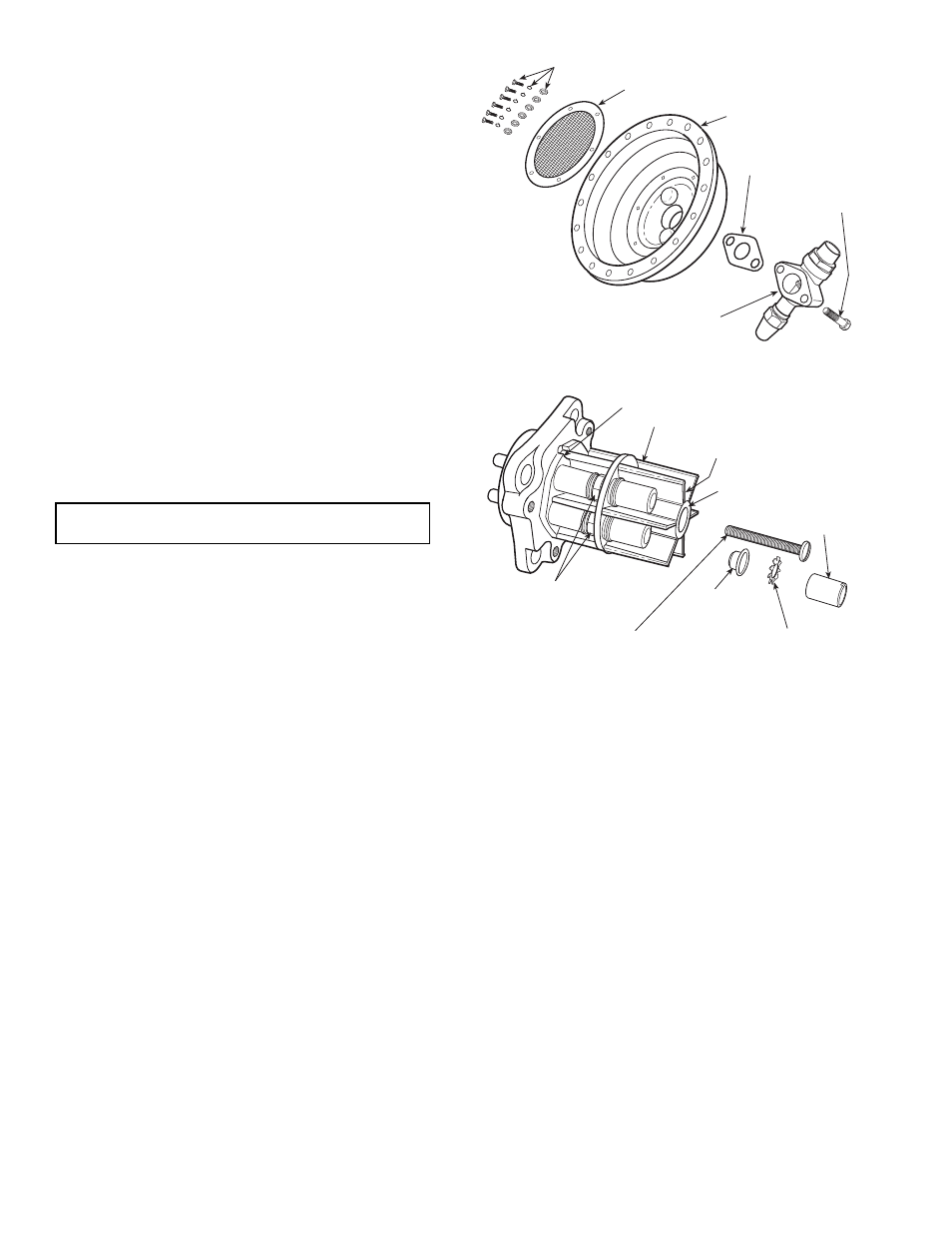
Cleaning Suction Strainer
1. Pump down compressor.
2. Remove motor end cover and screws holding disc type
strainer (Fig. 18) to cover.
3. Clean strainer with solvent or replace if broken or
corroded.
4. Replace strainer and motor end cover. Purge or evacuate
compressor before starting.
Motor Replacement —
Stator and rotor are not field
replaceable. Stator is a press fit into motor housing. If compres-
sor motor is damaged, replace compressor.
Terminal Plate Assembly —
The terminal plate assem-
bly is shown in Fig. 19. Do not disassemble for any reason ex-
cept to replace the phase barrier, which may become damaged.
If refrigerant leakage or a ground short occurs, the entire ter-
minal plate assembly must be replaced.
If it becomes necessary to remove the phase barrier, proceed
as follows:
1. Loosen and remove all terminal nuts.
2. Remove lock washers and wire terminals.
3. Loosen and disengage the center screw. (Do not try to
remove the screw.)
4. Lift the phase barrier off the terminal screws (the spacers
and the center screw are removed with the phase barrier).
Procedure for reassembling the phase barrier:
1. Place phase barrier over the terminal screws. Be sure po-
sitioning key is in the recess in the terminal plate before
proceeding further.
2. Place the spacers and wire terminals on the terminal
screws.
3. Place the lock washers and terminal nuts over the wire
terminals and tighten to specified torque (18 to 30 lb-in.).
4. Install the center screw through the phase barrier and
tighten to the specified torque (15 to 25 lb-in.).
NOTE: The design allows for clearance between the center
screw head and the phase barrier. Thus, the torque limit may
be reached before the screw head contacts the phase barrier.
This condition is acceptable.
Compressor Running Gear Removal
1. Remove pump end bearing head.
2. Remove motor end cover carefully to prevent damage to
stator. Support cover and lift off horizontally until it clears
windings.
3. Remove bottom cover plate.
4. Remove equalizer tube assembly from motor end of
crankshaft (or eccentric shaft). If shaft turns, preventing
tube assembly from being loosened, block shaft with a
piece of wood.
5. Remove rotor using a jackbolt. Insert a brass plug into
rotor hole to protect end of crankshaft from jackbolt.
Support rotor while it is being removed to prevent stator
damage.
6. Remove connection rod caps from compressors using
connecting rods and crankshafts. Label caps and rods so
they may be reinstalled in same plate on crankshaft.
7. Remove bolts holding counterweights and eccentric strap
side shields to eccentric shaft. Remove eccentric strap
side shields. Remove pump end counterweight through
pump end bearing head opening. Motor end counter-
weight will remain on eccentric shaft until shaft is
removed.
8. Pull eccentric shaft or crankshaft out through pump end
opening. Guide eccentric straps from eccentric shaft
during removal process. Rotate shaft and tap it lightly to
prevent straps from jamming.
9. Remove eccentric straps or connecting rods and pistons
through bottom cover plate opening.
10. Disassemble connecting rods or eccentric straps from
pistons by removing lock ring(s) and piston pins. Remove
oil and compression rings from piston. Keep each piston
assembly together for proper reassembly.
Check all parts for wear and tolerances shown in Table 6.
Check crankshaft (eccentric shaft) oil passages and clean if
clogged.
IMPORTANT: Do not disturb the jam nuts on which the
phase barrier rests.
STRAINER SCREWS & WASHERS
SUCTION STRAINER
MOTOR END COVER
VALVE GASKET
SUCTION SERVICE VALVE
VALVE CAP
SCREW
BARRIER POSITIONING KEY (THIS SIDE IS
ADJACENT TO THE CYLINDER HEAD)
PHASE BARRIER
NO TERMINAL IN
THIS SECTION
TERMINAL NUMBERS ON
THIS SURFACE
TERMINAL
NUT(TYP)
LOCK WASHER
(TYP)
BLACK JAM NUTS
ON TERMINALS 8 & 9;
BRASS JAM NUTS ON
TERMINALS 1, 2 AND 3
CENTRAL SCREW (THREADS
INTO TERMINAL PLATE)
SPACER
(TYP)
Fig. 18 — Motor End Cover Assembly
ACROSS-THE-LINE APPLICATION (5 TERMINALS)
Fig. 19 — Terminal Plate Assembly