Carrier 06D User Manual
Page 15
15
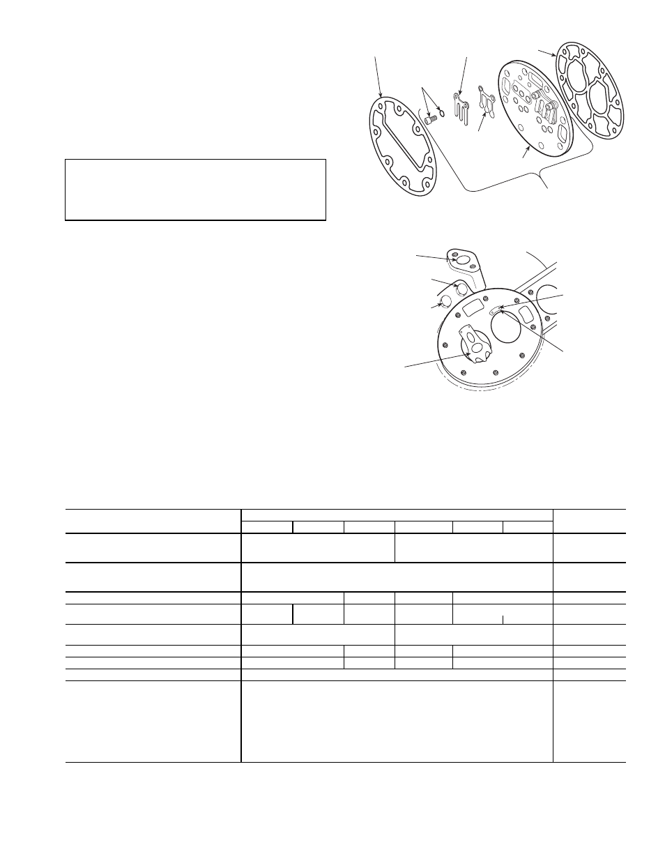
Suction and Discharge Valve Plate Assembly
(Fig. 16) —
Test for leaking discharge valves by pumping
compressor down and observing suction and discharge
pressure equalization. If a discharge valve is leaking, the
pressures will equalize rapidly. Maximum allowable discharge
pressure drop is 3 psi per minute after an initial drop of 10 to
15 psi in the first half minute.
If there is an indicated loss of capacity and discharge valves
check properly, remove suction and discharge valve plate
assembly and inspect suction valves.
DISASSEMBLY — Remove cylinder head.
1. Remove discharge valve assembly: cap screws, valve
stops, valve stop supports and valves.
2. Pry up on side of valve plate, between valve plate and
cylinder deck, to remove valve plate and expose suction
valves. Remove suction valves and suction valve posi-
tioning springs from dowel pins.
Inspect valves and valve seats for wear and damage. See
Table 6. Check cylinder deck valve stops for uneven wear.
Replace valves if cracked or worn. If valve seats are worn,
replace complete valve plate assembly. If cylinder deck valve
stops are worn, replace compressor.
REASSEMBLY — Do not interchange valves. Install suction
valve positioning springs on dowel pins. Assemble positioning
springs with spring ends bearing against cylinder deck
(Fig. 17). Springs bow upward. Place suction valves on dowel
pins, over positioning springs. Place valve plate on cylinder
deck, and reinstall discharge valve plate assembly. Retorque
discharge valve stop cap screws to 16 lb-ft. Replace cylinder
head. Be sure cylinder head gasket is lined up correctly with
cylinder head and valve plate.
Table 6 — Compressor Wear Limits (Factory Tolerances) (in.)
*Maximum allowable wear above maximum or below minimum factory tolerances
shown. For example: difference between pump end main bearing diameter and
journal diameter is .001 in. (1.3745 – 1.3735) per factory tolerances. Maximum
allowable difference is .004 in. (.002 + .002).
†Tolerance for the 06DA825 same as 06DA824.
IMPORTANT: This test procedure is not applicable to
compressors equipped with pressure actuated or solenoid
unloader valves due to rapid pressure equalization rate.
Check suction and discharge valves by disassembling
valve plate (see Fig. 16).
COMPRESSOR PART
COMPRESSOR MODEL
MAX* ALLOW
WEAR
06DM808
06DM313
06DA818
06DA825†
06DA328
06DA537
MOTOR END
Main Bearing Diameter
Max
1.3755
1.6240
0.002
Journal Diameter
Min
1.3735
1.6233
0.002
PUMP END
Main Bearing Diameter
Max
1.3745
0.002
Journal Diameter
Min
1.3735
0.002
CRANKPIN DIAMETER
Min
2.2030
1.3735
2.2030
1.3735
0.0025
THROW
Max
1.2500
1.0000
1.4374
1.2500
1.9396
—
Min
1.2460
—
1.4344
1.246
—
—
—
THRUSTWASHER
Max
—
0.1570
0.025
Min
—
0.1550
0.025
ECCENTRIC DIAMETER
Max
2.2035
—
2.2035
—
0.002
CONN. ROD DIAMETER
Max
—
1.3755
—
1.3755
0.002
PISTON PIN BEARING
Min
0.6878
0.001
CYLINDERS
Bore
Max
2.0005
0.002
Piston Diameter
Min
1.996
0.002
Piston Pin Diameter
Min
0.6873
0.001
Piston Pin Bearing
Press Fit
—
Piston Ring Gap
Max
0.0130
0.025
Min
0.0050
0.025
Piston Ring Side Clearance
Max
0.0020
0.002
Min
0.0010
0.002
CYLINDER HEAD
GASKET
VALVE PLATE
GASKET
DISCHARGE VALVE
SCREW AND
LOCK WASHER
DISCHARGE
VALVE
VALVE PLATE
VALVE PLATE ASSEMBLY
DISCHARGE
VALVE STOP
DISCHARGE
PORT
HIGH-PRESSURE
CONNECTION
LOW-PRESSURE
CONNECTION
SUCTION
VALVE
VALVE PLATE
DOWEL PIN
SUCTION VALVE
POSITIONING
SPRING
Fig. 16 — Valve Plate Assembly
Fig. 17 — Suction Valve and Positioning
Springs in Place