Capacity control pressure (fig. 8), Condenser maintenance – Carrier 06D User Manual
Page 10
10
Table 4 — Capacity Control Reduction Steps
Capacity Control Pressure (Fig. 8)
LOADED OPERATION — Pressure-operated control valve
is controlled by suction pressure and actuated by discharge
pressure. Each valve controls 2 cylinders (one bank). On
start-up, controlled cylinders do not load up until differential
between suction and discharge pressures is approximately
25 psi.
When suction pressure rises high enough to overcome
control set point spring, the diaphragm snaps to the left and
relieves pressure against the poppet valve. The drive spring
moves the poppet valve to left and it seats in the closed
position.
With poppet valve closed, discharge gas is directed into the
unloader-piston chamber and pressure builds up against the
piston. When pressure against unloader piston is high enough
to overcome the unloader valve spring, piston moves valve to
the right, opening suction port. Suction gas can now be drawn
into the cylinders and the bank is running fully loaded.
UNLOADED OPERATION — As suction pressure drops
below set point, control spring expands, snapping diaphragm to
right. This forces poppet valve open and allows gas from
discharge manifold to vent through base of control valve to
suction side. Loss of full discharge pressure against unloaded
piston allows unloader valve spring to move valve left to
closed position. The suction port is blocked, isolating the
cylinder bank from the suction manifold. The cylinder bank is
now unloaded.
CONDENSER MAINTENANCE
To inspect and clean condenser, drain water and remove
condenser heads. To drain condenser, shut off water supply and
disconnect inlet and outlet piping. Remove drain plugs and
vent plug.
With condenser heads removed, inspect tubes for refrigerant
leaks. (Refer to Carrier Refrigerant Service Techniques Manual.)
Clean condenser tubes with nylon brush (available from
Carrier Service Department). Flush water through tubes while
cleaning. If hard scale has formed, clean tubes chemically. Do
not use brushes that will scrape or scratch tubes.
Because the condenser water circuit is usually an open
system, the condenser tubes may be subject to contamination
by foreign matter. Local water conditions may cause excessive
fouling or pitting of tubes. Condenser tubes, therefore, should
be cleaned at least once a year or more often if the water is
contaminated.
Proper water treatment can minimize tube fouling and
pitting. If such conditions are anticipated, water treatment
analysis is recommended. Refer to the Carrier System Design
Manual, Part 5, for general water conditioning information.
If hard scale has formed, clean the tubes chemically. Con-
sult an experienced and reliable water-treatment firm in your
area for treatment recommendations. Clean the condenser by
gravity or by forced circulation as shown in Fig. 9 and 10.
UNIT 06D,07D
NO. OF
CONTR
CYL
% Full Load Capacity
100
67
49
32
% Full Load kW
100
73
57
46
Number of Active Cylinders
ALL 4 CYLINDER
MODELS
2
4
—
2
—
ALL 6 CYLINDER
MODELS
4
6
4
—
2
IMPORTANT: If the ambient temperature is below 32 F
during a shutdown period; protect the condenser from
freezing by draining the water from the system or by add-
ing antifreeze to the water.
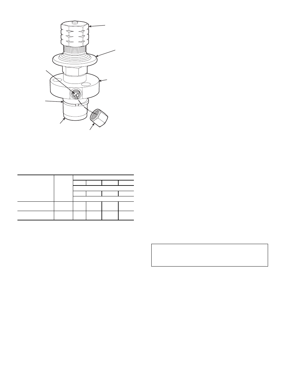
BYPASS PISTON-USED
WITH HOT GAS BYPASS
TYPE OF UNLOADING ONLY.
NOT REQUIRED WITH
SUCTION CUTOFF TYPE
UNLOADING.
DIFFERENTIAL SCREW
SEALING CAP (CAP MUST
BE REPLACED TO PREVENT
REFRIGERANT LEAKAGE)
BYPASS
PISTON RING
PRESSURE
DIFFERENTIAL
ADJUSTMENT
SCREW
POWER
HEAD
VALVE BODY
CONTROL
SET POINT
ADJUSTMENT
NUT
Fig. 7 — Capacity Control Valve
(Pressure Type)