2 board layout – Texas Instruments SLLU039B User Manual
Page 25
Board Layout
3-3
Bill of Materials, Board Layout, and PCB Construction
3.2
Board Layout
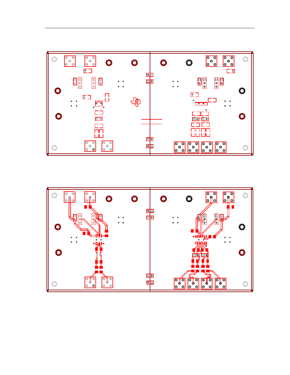
Figure 3−1. Assembly Drawing
GND01
VCC01
VCC
GND
VCC01
GND01
GND
VCC
VCC
GND
GND01
VCC01
TEXAS INSTRUMENTS
A/W NO. # 6424409B
PWA. EVM.
SN65MLVD
SERIAL NO.
MADE
IN
U.S.A.
GND
VCC
VCC01
GND01
GND01
VCC01
GND
VCC
U1
J10
J9
J8
J7
J6
J4
J3
J2
J1
J17
J15
J13
J11
J18
J16
J14
J12
R14
R12
R3
R1
R13
R2
W4 W3
W2 W1
W10
W9
W8
W7
TP4
TP3
TP1
P3
P2
P1
TP2
R16
R15
R7
R6
R5
R4
R18
R17
R11
R8
R9
J5
R10
U2
The top layer of the EVM contains the controlled impedance and matched
length traces.
Figure 3−2. Top Layer
See also other documents in the category Texas Instruments Hardware:
- Digital Signal Processor SM320F2812-HT (153 pages)
- MSP430x1xx (440 pages)
- Laser And Motor Drives DRV8811EVM (13 pages)
- TMS320 DSP (88 pages)
- MSP430x11x1 (45 pages)
- TVP5154EVM (55 pages)
- TMS320DM646X DMSOC (64 pages)
- CC2511 (24 pages)
- SN65HVS880 (4 pages)
- TPS650231EVM (14 pages)
- TMS320TCI648x (256 pages)
- TSC2007EVM-PDK (16 pages)
- UCC38500EVM (16 pages)
- TMS320C6000 (62 pages)
- SCAU020 (21 pages)
- TPS40051 (17 pages)
- TNETE2201 (14 pages)
- TMS320C64x DSP (306 pages)
- UCC2891 (21 pages)
- TMS320C3x (757 pages)
- MSP430 (138 pages)
- TMS320C6712D (102 pages)
- MSP430x4xx (512 pages)
- TMS320C6454 (225 pages)
- SPRU938B (48 pages)
- TUSB3210 (22 pages)
- TMS320C6457 (43 pages)
- CC2530ZNP (3 pages)
- TMS320C6455 (50 pages)
- TSB12LV26 (91 pages)
- TMS320C6472 (2 pages)
- VLYNQ Port (49 pages)
- TMS380C26 (92 pages)
- MSP-FET430 (95 pages)
- TMS320TCI6486 (160 pages)
- TPS2330 (22 pages)
- DM648 DSP (47 pages)
- TMS320DM36X (134 pages)
- MSC1211 (35 pages)
- SPRAA56 (29 pages)
- DAC7741EVM (28 pages)
- CDCM7005 (34 pages)
- TMS370 (99 pages)
- Adpater (37 pages)
- TMS320C6452 DSP (46 pages)