1 bill of materials, Table 3−1. m-lvds evm bill of materials – Texas Instruments SLLU039B User Manual
Page 24
Bill of Materials
3-2
Bill of Materials, Board Layout, and PCB Construction
3.1
Bill of Materials
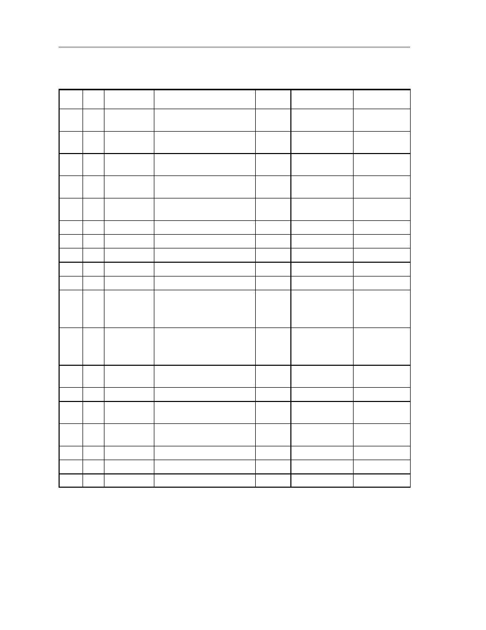
Table 3−1. M-LVDS EVM Bill of Materials
Item
No.
Qty.
Reference
Designation
Description
MFG
Part #
Not Installed
1
2
C1, C2
Capacitor, SMT1206, 50 V, 10%,
0.01
µ
F
AVX
12101C103JATMA
2
4
C5, C6, C9,
C10
Capacitor, SMT1206, 16 V, 10%,
1
µ
F
AVX
1206YC105KAT
3
4
C3, C4, C7, C8
Capacitor, SMT1210, 10 V, 10%,
10
µ
F
AVX
1210ZG106ZAT2A
4
2
J11, J13, J15,
J17
Banana jack, red
Allied
ST−351A
J11, J15
5
2
J12, J14, J16,
J18
Banana jack, black
Allied
ST−351B
J12, J16
6
4
J1 − J 10
Connector
Allied
713−4339
J3 − J6, J9, J10
7
4
TP1 − TP4
Header (make from 4−103239−0)
AMP
4−103239−0x2
8
3
P1 − P3
Header (make from 4−103239−0)
AMP
4−103239−0x2
9
4
W7 − W10
Header (make from 4−103239−0)
AMP
4−103239−0x2
10
4
W1 − W4
Header (make from 4−103239−0)
AMP
4−103239−0x3
11
1
U1
IC, SMT, 14P, High speed 50-
Ω
line driver/receiver
TI
†
SN65MLVD202AD
SN65MLVD205AD
SN65MLVD203D
SN65MLVD207D
12
1
U2
IC, SMT, 8P High speed 50-
Ω
line driver/receiver
TI
†
SN65MLVD200AD
SN65MLVD204AD
SN65MLVD201D
SN65MLVD206D
13
2
R1, R3, R12,
R14
Resistor, SMT, 1/4 W, 1%, 49.9
Ω
Dale
CRCW121049R9F
R1, R12
14
2
R2, R13
Resistor, SMT, 1/4 W, 1%, 453
Ω
Dale
CRCW12104530F
15
6
R8 − R11, R17,
R18
Resistor, SMT, 1/4 W, 1%, 0.0
Ω
Dale
CRCW12100000F
R8 − R11, R17,
R18
16
6
R4 − R7, R15,
R16
Resistor, SMT, 1/4 W, 1%, 100
Ω
Dale
CRCW12101000F
17
4
1/2” nylon, hex, standoff
Keystone
1902C
18
4
Phillips, pan head, screw
H703−ND
19
8
Jumper, shorting
†
Only one will be installed.