Texas Instruments SLLU039B User Manual
Page 22
Test Results
2-6
Test Setup
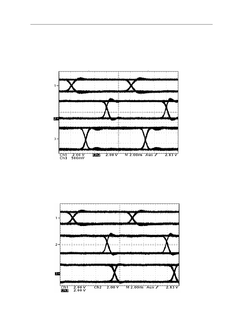
signal on TP1, R2 is shorted. Type-2 behavior is again observed on the
SN65MLVD207 receiver output.
Trace three shows the differential voltage on the bus. Note that the bus volt-
ages are nominal M-LVDS levels of 1.1 V
PP
due to the lower load seen by the
current driver.
Figure 2−5. Parallel Terminated Point-to-Point Parallel Simplex Typical Eye Pattern Data
Driver
Input
Receiver
Output
Differential
Bus
Voltage
Figure 2−6 represents the two-node multipoint transmission eye patterns
where trace 1 is the input signal applied to J2, and traces 2 and 3 are the output
signals seen at TP1 and TP3 respectively with R2 and R13 shorted. The offset
zero-crossing shows the difference between Type−2 (Receiver #1 Output) and
Type−1 (Receiver #2 Output).
Figure 2−6. Two-Node Multipoint Typical Eye Pattern Data
Driver
Input
Receiver #1
Output
Receiver #2
Output
- Digital Signal Processor SM320F2812-HT (153 pages)
- MSP430x1xx (440 pages)
- Laser And Motor Drives DRV8811EVM (13 pages)
- TMS320 DSP (88 pages)
- MSP430x11x1 (45 pages)
- TVP5154EVM (55 pages)
- TMS320DM646X DMSOC (64 pages)
- CC2511 (24 pages)
- SN65HVS880 (4 pages)
- TPS650231EVM (14 pages)
- TMS320TCI648x (256 pages)
- TSC2007EVM-PDK (16 pages)
- UCC38500EVM (16 pages)
- TMS320C6000 (62 pages)
- SCAU020 (21 pages)
- TPS40051 (17 pages)
- TNETE2201 (14 pages)
- TMS320C64x DSP (306 pages)
- UCC2891 (21 pages)
- TMS320C3x (757 pages)
- MSP430 (138 pages)
- TMS320C6712D (102 pages)
- MSP430x4xx (512 pages)
- TMS320C6454 (225 pages)
- SPRU938B (48 pages)
- TUSB3210 (22 pages)
- TMS320C6457 (43 pages)
- CC2530ZNP (3 pages)
- TMS320C6455 (50 pages)
- TSB12LV26 (91 pages)
- TMS320C6472 (2 pages)
- VLYNQ Port (49 pages)
- TMS380C26 (92 pages)
- MSP-FET430 (95 pages)
- TMS320TCI6486 (160 pages)
- TPS2330 (22 pages)
- DM648 DSP (47 pages)
- TMS320DM36X (134 pages)
- MSC1211 (35 pages)
- SPRAA56 (29 pages)
- DAC7741EVM (28 pages)
- CDCM7005 (34 pages)
- TMS370 (99 pages)
- Adpater (37 pages)
- TMS320C6452 DSP (46 pages)