Connections, Connections 6 – Interlogix TruVision IP Open Standards Box User Manual User Manual
Page 10
1BChapter 2: Installation
Connections
A qualified service person, complying with all applicable codes, should perform
all required hardware installation.
Note
: Do not attempt to extend the power/data cable connection using RJ45
couplers and Cat5 cable. Only use the data cable connection provided.
Note
: Use 12 VDC or PoE.
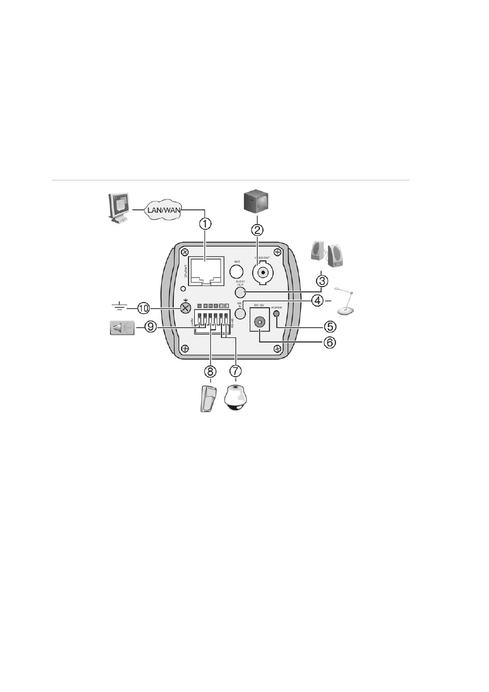
Figure 3: Wiring the camera
1. Ethernet RJ45 PoE port
Connect to network devices.
2. Video
output
Connect to a CCTV monitor.
3. Audio
output
Connect to an audio output.
Line level, 600 Ω.
4. Audio
input
Connect to an audio input.
2.0 to 2.4 Vp-p, 1 kΩ.
5. Power
LED
Illuminated when power is connected.
6. Power
supply
Connect +12 VDC power supply.
7. RS-485 D+, D-
Connect to an RS-485 device such as a
PTZ dome camera.
8. Alarm outputs
Connect 1A/1B and 2A/2B to alarm output
devices.
9. Alarm
inputs
Connect IN1/GND and IN2/GND to alarm
input devices.
10. Ground
Connect to ground.
Note:
The alarm output can be used to turn on and off an external alarm device.
Connect a 12 VDC/30 mA external power supply to the alarm output. See
Figure 4 below.
6
TruVision IP Cam Open-Standards User Manual