Selecting the coverage pattern – Interlogix AP450 User Manual
Page 2
3. Pull up on the top edge of the electronics module while
rocking down on the lower edge to remove the module
from the base. Be careful not to touch the pyroelectric
sensor located on the bottom of the module. See Figure 3
4. Select mounting holes for corner or wall mounting. Use the
base as a template for marking screw hole locations on
the wall. See Figure 3 below.
5. Strip the cable for 2 inches (5cm) and pull it through the
cable entry hole(s) and strain relief. Make sure that the
cable has slack in the wall. See Figure 3 below.
6. Use screws and wall anchors, if necessary, to attach the
base to the wall.
7. Select the appropriate coverage pattern. See “Selecting
8. Replace the electronics module by lining up the notches
on the module with the module notch guides and press the
top of the module down until it snaps into the module
9. Strip 1/4 inch (0.6cm) of insulation from each wire. Insert
each wire into the appropriate terminal and tighten screws.
10. Set the sensitivity, range and LED jumpers for the
application desired. See Figure 7 and “Setting the
sensitivity, range, and LED” on page 3
11. To replace the cover, insert the closing tabs at the bottom
of the cover into the guides at the bottom of the base and
snap the cover down. Insert the screw. Fit the hole in the
cover plate over the LED and snap the cover plate into
place. See Figure 1 on page 1.
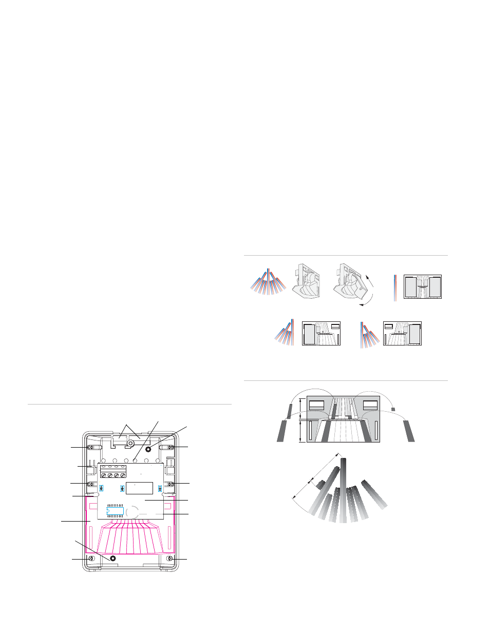
Figure 3: Base
Cable entry
holes
Cable strain
relief
Flat wall mount
knockout
Corner mount
knockout
Flat wall mount
knockout
Corner mount
knockout
Corner mount
knockout
Corner mount
knockout
Corner mount
knockout
Corner mount
knockout
Mirror
Electronics
module
Pyroelectric
sensor
Module notch
guide
Module guide
Selecting the coverage pattern
The coverage pattern for the unit can be modified to fit specific
applications by masking off mirror curtains. Curtains should be
masked to avoid sources of false alarms, such as heaters, air
conditioners, and windows.
If necessary, use one or more of the following methods to
modify the coverage pattern:
•
Use one or both of the plastic masks provided to mask off
large areas of coverage as shown in Figure 4 below.
•
Mask the appropriate mirror curtains with the adhesive
labels provided. See the example shown in Figure 5
below. Do not use sharp objects to remove unwanted
labels. If necessary, carefully peel the label off.
•
Use the cardboard undercrawl window mask to improve
false alarm immunity in the presence of objects within 5
feet (1.5m) and directly under the sensor. See Figure 6 on
Figure 4: Plastic masks
2
1
2
1
Figure 5: Adhesive labels
A
B
9
1
A
B
1
2
3
4
5
6
7
8
2
3
4
5
6
7
8
9
9
8
7
6
5
4
3
2
1
2
AP450 Motion Sensors Installation Instructions