Mode dip switch, Co/cpe, Mode dip switch 6 – Interlogix MCR200-1T/1CX User Manual
Page 12: Co/cpe 6
6 IFS MCR200-1T/1CX User Manual
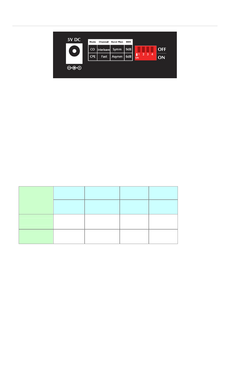
Figure 2: Rear Panel
Mode DIP Switch
The MCR200-1T/1CX provides 4 selective transmission
modes. By switching the transmission modes, you can obtain
the best transmission mode to suit your cable quality or
distance of connectivity. The following is a summary table of
transmission settings, bandwidth and distance extensibility
tested for AWG 24 (0.5mm) twisted-pair without noise and
cross talk.
DIP-1
DIP-2
DIP-3
DIP-4
Mode
Channel
Band
Plan
SNR
OFF CO
Interleave Symm
9dB
ON
(default)
CPE
Fast Asymm 6dB
CO/CPE
CO (Central Office) – the Master device mode, usually the CO
device will be located at the data center of an ISP or enterprise
to link to the backbone. For security surveillance applications,
the CO setting should be selected for use at the IP camera
location to allow for maximum bandwidth utilization of video
streaming.
CPE (Customer Premises Equipment) – the Slave device
mode, usually the CPE device will be located at branch office,