Configure trigger dip - switches – Haltech F9A User Manual
Page 25
24
1.3.10. Configure Trigger DIP - Switches
The input trigger is used by the F9 to determine engine speed and when to fire the injectors.
The standard connection for this wire is to the negative terminal of the ignition coil. If the
engine does not use standard points or a electronic ignition system then it may be necessary to
reconfigure the input circuit. The trigger configuration DIP switches can be found by
removing the back cover from the F9 ECU. Refer to the following tables (see below) for DIP
switch functions and settings.
Switch 1 ON: Adds 1k pull-up resistor to battery.
Use an open collector (digital) outputs.
Switch 2 ON: Engage primary filter capacitor.
Switch 3 ON: Engage secondary filter capacitor.
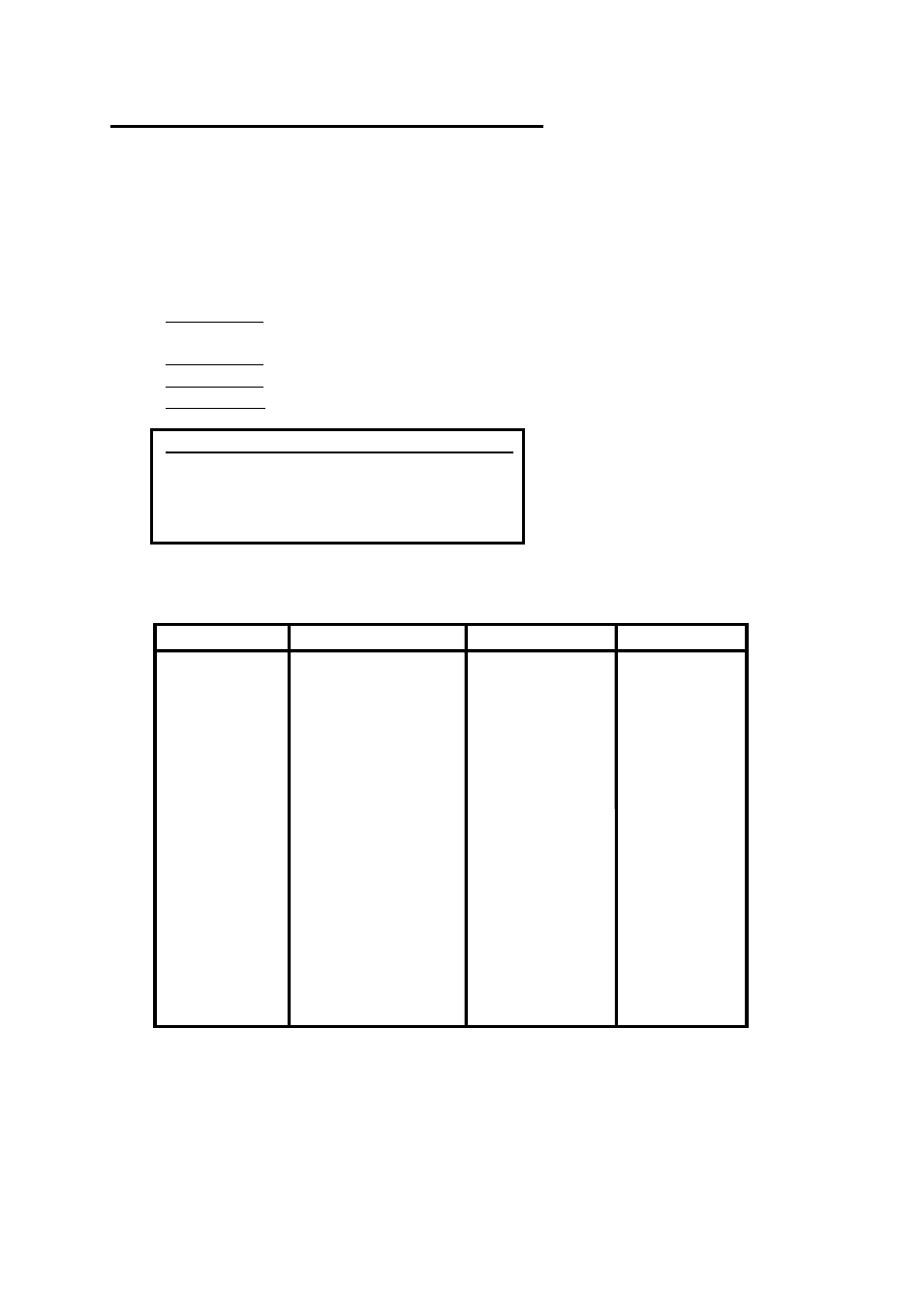
Switch 4 & 5: Changes trigger threshold level (see below)
Trigger level
Switch 4
Switch 5
+5.0
Volts
OFF
OFF
+3.4
Volts
ON
OFF
+2.5
Volts
OFF
ON
+2.0
Volts
ON
ON
Refer to the following tables for switch settings for common ignition systems. All ECU’s are
factory set for Category A ignition systems.
Category A
Category B
Category C Category D
Points style
MSD 6A/6T
Firepower ECI Porsche 911/930
Transistor
MSD
7AL/7x
Buick
Indy
Assisted Direct
Fire
Direct
Fire
MSD
8
GM
MSD
GM HEI
Electromotive
Jacobs
Stinger
1
Stinger
Thermo-Fire
(Most
Others)