Receiver installation, Connect the throttle linkage, Install receiver and battery – Great Planes Ultra Sport 40 ARF Red - GPMA1005 User Manual
Page 22: Attach the antenna
the carburetor on the four cycle is turned around. A new
hole may need to be drilled if your engine throttle linkage
requires a different setup. Trial fit the throttle pushrod
guide tube. There should be 1/2" of tube protruding from
the firewall and less than 1/8" from the fuselage former.
Sand the tube near both ends and glue the tube into the
fuselage with 6-minute epoxy.
Connect the Throttle Linkage
2. (2-stroke Linkage) Thread a clevis onto the
throttle pushrod. Place the clevis in the outermost hole on
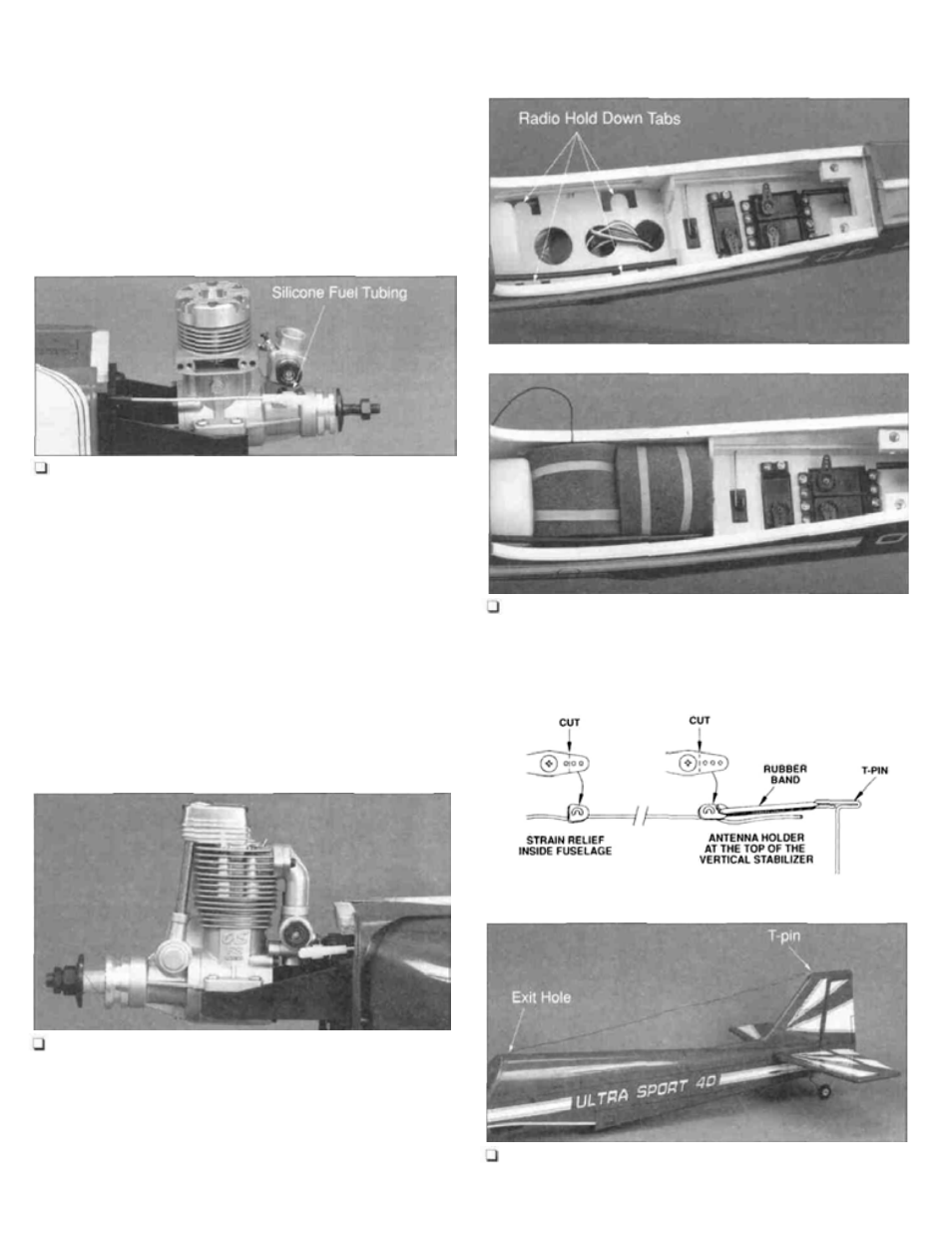
the throttle arm and secure with 1/4" of silicone fuel tubing.
Place the throttle in the half open position and place a
mark above the servo arm hole in the radio compartment.
Cut the pushrod 1/4" past the mark. Make an L-bend in the
pushrod at the mark and insert it into the servo arm,
securing it with a pushrod keeper.
Receiver Installation
Install Receiver and Battery
1. Wrap the radio receiver and battery in protective
foam. Using #64 rubber bands secure the receiver and
battery in the radio compartment. There are four radio hold
down tabs in the radio compartment to attach the rubber
bands to.
Connect the Throttle Linkage
3. (4-stroke Linkage) Thread a clevis onto the
throttle pushrod. Place the clevis in the inside hole on the
throttle arm and secure with 1/4" of silicone fuel tubing.
Place the throttle in the half open position and place a
mark above the servo arm hole in the radio compartment.
Cut the pushrod 1/4" past the mark. Make an L-bend in the
pushrod at the mark and insert it into the servo arm,
securing it with a pushrod keeper.
Attach the Antenna
2. Route the antenna under the servo tray and up
through an exit hole made with a T-pin behind the pilot in
22